Home
› Power Outlet Wiring Diagram - Wiring Diagrams for GFCI Outlets - Do-it-yourself-help.com : It shows the components of the circuit as simplified shapes, and the power and signal connections between the devices.
Power Outlet Wiring Diagram - Wiring Diagrams for GFCI Outlets - Do-it-yourself-help.com : It shows the components of the circuit as simplified shapes, and the power and signal connections between the devices.
Power Outlet Wiring Diagram - Wiring Diagrams for GFCI Outlets - Do-it-yourself-help.com : It shows the components of the circuit as simplified shapes, and the power and signal connections between the devices.. Deviate relay location and fuseplacements as well as the locations of multiple connectors see section component locations. Wiring a gfci outlet may vary slightly from manufacturer to manufacturer, but for the most part, they follow the same general principles. It shows the components of the circuit as simplified shapes, and the power and signal connections between the devices. Find out which kinds of diagrams serve which purpose before you try to use them. Different switches and different types of outlets all have different symbols, and you'll need to know these symbols in order to be able to read an electrical wiring diagram.
When wiring a wall outlet the neutral (white) wire should connect to the white or silver metal screw. Click the icons below to. 220 electrical outlet wiring best 240 volt plug wiring. Not all wiring diagrams are the same. Wiring parallel circuit lights with switch on other end be careful cause when there's a series of lights between the switch(es) and the power supply the wiring is a little bit.
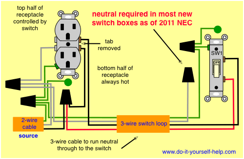
How To Wire A Switched Outlet Power To Receptacle from www.chanish.org Wiring parallel circuit lights with switch on other end be careful cause when there's a series of lights between the switch(es) and the power supply the wiring is a little bit. Related content for toyota corolla2004. Wiring diagram of a switched electrical receptacle outlet and an unswitched electrical receptacle outlet with the power entering the switched outlet electrical box from the circuit breaker panel. Now in the diagram here, the power source is coming in from the bottom/left. Power outlet (12v), from september 1998. Different switches and different types of outlets all have different symbols, and you'll need to know these symbols in order to be able to read an electrical wiring diagram. Find out which kinds of diagrams serve which purpose before you try to use them. Wiring diagrams for electrical receptacle outlets.
How an outlet circuit works.
Multiple outlet in serie wiring diagram : Simple home electrical wiring diagrams. Related content for toyota corolla2004. Wiring diagrams for electrical receptacle outlets. This might seem intimidating, but it does not have to be. A wiring diagram is a simple visual representation of the physical connections and physical layout of an electrical system or circuit. Using the outlet wires, ground (usually green or bare copper wire) goes to the green screw. Now in the diagram here, the power source is coming in from the bottom/left. You could be a service technician who wishes to try to find recommendations or or you are a trainee, or perhaps even you that just would like to know regarding 12 volt power outlet wiring diagram. It shows the components of the circuit as simplified shapes, and the power and signal connections between the devices. 12 volt power outlet wiring diagram. Looking to have an outlet be controlled by a switch? Jan 24, 18 02:09 pm.
220 electrical outlet wiring best 240 volt plug wiring. Wiring a combo switch outlet circuit is easy to do if you understand a few key features of the combo switch outlet. Wiring diagram of a switched electrical receptacle outlet and an unswitched electrical receptacle outlet with the power entering the switched outlet electrical box from the circuit breaker panel. When wiring a wall outlet the neutral (white) wire should connect to the white or silver metal screw. Looking to have an outlet be controlled by a switch?
Wiring Diagram Outlets. Beautiful Wiring Diagram Outlets. Splendid Line Wiring Diagram Help ... from i.pinimg.com The figure below displays the ring main wiring diagram for electric power outlets. Wiring a combo switch outlet circuit is easy to do if you understand a few key features of the combo switch outlet. 220 electrical outlet wiring best 240 volt plug wiring. It shows the components of the circuit as simplified shapes, and the power and signal connections between the devices. Test the outlet with a circuit tester to verify that the power is indeed off (there's nothing worse than finding out the hard way). Using the outlet wires, ground (usually green or bare copper wire) goes to the green screw. When wiring a wall outlet the neutral (white) wire should connect to the white or silver metal screw. Any break or malfunction in one outlet will cause all the other outlets to fail.
Power outlet (12v), from september 1998.
Multiple outlet in serie wiring diagram : Using the outlet wires, ground (usually green or bare copper wire) goes to the green screw. This page is a favor for any person trying to wire switches, lights and outlets together! Wiring a combo switch outlet circuit is easy to do if you understand a few key features of the combo switch outlet. Wiring diagram outlets awesome volt ac wiring colors of. Wiring parallel circuit lights with switch on other end be careful cause when there's a series of lights between the switch(es) and the power supply the wiring is a little bit. Searching for information regarding 12 volt power outlet wiring diagram? Power outlet (12v), from september 1998. The diagram will show how a standard switched duplex receptacle is wired. 1 form a c : Looking to have an outlet be controlled by a switch? The single pole switch has a neutral conductor for future electronic controls such as a timer or a wifi switch. There are three wires, shown in the diagram as blue, white, and.
Find out which kinds of diagrams serve which purpose before you try to use them. Pick the diagram that is most like the scenario you are in and see if you can wire your switch! Notice the black wire is the only wire that we are controlling through. Click the icons below to. Make sure, however, to always turn power off at the main circuit panel before doing any electrical wiring.
How To Wire An Outlet In Series | MyCoffeepot.Org from waterheatertimer.org Wiring a light switch wiring diagram: 12 volt power outlet wiring diagram. Jan 24, 18 02:09 pm. For example, a home builder will want to confirm the physical location of electrical outlets and light fixtures using a wiring diagram to avoid costly mistakes and building. Looking to have an outlet be controlled by a switch? The outlet should also have a wiring diagram that is usually available online with a paper copy provided with the outlet itself. Power outlet (12v), from september 1998. Related content for toyota corolla2004.
A wiring diagram is a simple visual representation of the physical connections and physical layout of an electrical system or circuit.
Notice the black wire is the only wire that we are controlling through. The outlet should also have a wiring diagram that is usually available online with a paper copy provided with the outlet itself. It shows the components of the circuit as simplified shapes, and the power and signal connections between the devices. You could be a service technician who wishes to try to find recommendations or or you are a trainee, or perhaps even you that just would like to know regarding 12 volt power outlet wiring diagram. The power can come from either the switch box or the fixture box and a set of electrical switch wiring diagrams will explain each of these scenarios to you clearly. Wiring a light switch wiring diagram: Now in the diagram here, the power source is coming in from the bottom/left. Searching for information regarding 12 volt power outlet wiring diagram? This page contains wiring diagrams for household light switches and includes: Deviate relay location and fuseplacements as well as the locations of multiple connectors see section component locations. 1 form a c : Wiring diagram of a switched electrical receptacle outlet and an unswitched electrical receptacle outlet with the power entering the switched outlet electrical box from the circuit breaker panel. There are three wires, shown in the diagram as blue, white, and.