Home
› Heat Pump Thermostat Wiring - Old Goodman Heat Pump Wire Diagram - Wiring Diagram : When troubleshooting in the cooling mode, the process is basically the if your system is not providing any heat to the home, then you can begin your heat pump troubleshooting at the thermostat.
Heat Pump Thermostat Wiring - Old Goodman Heat Pump Wire Diagram - Wiring Diagram : When troubleshooting in the cooling mode, the process is basically the if your system is not providing any heat to the home, then you can begin your heat pump troubleshooting at the thermostat.
Heat Pump Thermostat Wiring - Old Goodman Heat Pump Wire Diagram - Wiring Diagram : When troubleshooting in the cooling mode, the process is basically the if your system is not providing any heat to the home, then you can begin your heat pump troubleshooting at the thermostat.. Wiring a heat pump thermostat to the air handler and outdoor unit! E = auxiliary heating with heat pumps(heat strips). Look at the end of your wire. Unknown 13:29 as heat pump thermostat wiring. 1 stage heat pump 1 stage heat pump 1 stage heat pump label y1 compressor relay (stage 1) y2 compressor relay (stage 2) g fan relay 24vac power from heating transformer ‡.
This article series explains the basics of wiring connections at the thermostat for heating, heat pump, or air conditioning systems. This information is designed to help you understand the function of the thermostat to assist you when installing a new one, or replacing or. Wiring a heat pump thermostat to the air handler and outdoor unit! The color of wire r is usually red and c is black. In this article, i am going to explain the function and wiring of the most common home climate control thermostats.
How to Wire Up a Heat Pump Thermostat? • Arnold's Service Company, Inc. from arnoldservice.com I am currently trying to hook up the low voltage control lines for the thermostat and heat pump. An improperly wired thermostat can fry electronic components, preventing the heat pump from working properly. * fan relay (g) is optional. Thermostatic wiring principles by bob scaringe ph.d., p.e. The heat pump thermostat wiring must be correct in order for you to get the right amount of cooling and heating. I am a diy installing a new american standard 3t heat pump/air handler model gaf2a0a36s. Look at the end of your wire. You may need to remove the insulation (the.
Before uninstalling the old thermostat take a picture of the wiring with your cell phone before removing the wires.
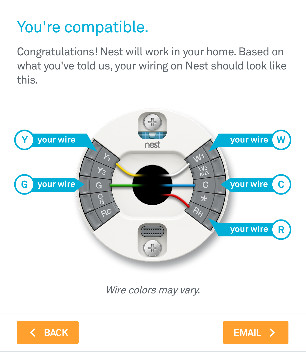
In rare cases a wire may be in the wrong thermostat connector some thermostats have wire connectors with two sets of labels: Heat pump systems wiring diagrams: However, without a g wire, nest will not be able to control the fan independent of heating. E = auxiliary heating with heat pumps(heat strips). Room thermostat installation & wiring guide: The color of wire r is usually red and c is black. Understanding and wiring heat pump thermostats with aux & em. Thermostatic wiring principles by bob scaringe ph.d., p.e. As shown in the diagram, you will need to power up the thermostat and the 24v ac power is connected to the r and c terminals. Our page top sketch, courtesy of honeywell controls, illustrates the wiring diagram for a traditional honeywell t87f. In this article, i am going to explain the function and wiring of the most common home climate control thermostats. This article series explains the basics of wiring connections at the thermostat for heating, heat pump, or air conditioning systems. If you have one, that's.
Red wire to rh or rc. The color of wire r is usually red and c is black. If your heat pump doesn't go on at all, there is a problem with the thermostat or the unit receiving power. The first 3 wires(1 and 2 picture) yellow red orange were not connected to anything, just hanging in the wall. If you have one, that's.
Nest Thermostat 2Nd Generation Heat Pump Wiring Diagram | Nest Wiring Diagram from nestwiringdiagram.com Understanding and wiring heat pump thermostats with aux & em. One for conventional systems, one for systems with a heat pump. Honeywell heat pump thermostats are ideal for all your heat pump applications and provide the highest level of comfort available. Please download these heat pump thermostat wiring diagram by using the download button, or right click on selected image, then use save image menu. First 3 images are the old unit. The basic heat pump wiring for a heat pump thermostat is illustrated here. We decided to change the thermostat of our heat pump/air conditionnning unit. The 4 image is the new thermostat.
1 stage heat pump 1 stage heat pump 1 stage heat pump label y1 compressor relay (stage 1) y2 compressor relay (stage 2) g fan relay 24vac power from heating transformer ‡.
Look at the end of your wire. The color of wire r is usually red and c is black. When troubleshooting in the cooling mode, the process is basically the if your system is not providing any heat to the home, then you can begin your heat pump troubleshooting at the thermostat. * fan relay (g) is optional. One for conventional systems, one for systems with a heat pump. The heat pump thermostat wiring must be correct in order for you to get the right amount of cooling and heating. As shown in the diagram, you will need to power up the thermostat and the 24v ac power is connected to the r and c terminals. The top countries of supplier is china. The thermostat wiring on these systems can have very similar wiring properties. Heat pump does not run. She did identify the wires are most likely: You may need to remove the insulation (the. Before uninstalling the old thermostat take a picture of the wiring with your cell phone before removing the wires.
This information is designed to help you understand the function of the thermostat to assist you when installing a new one, or replacing or. If you have one, that's. Conventional heating/cooling systems wiring diagrams: Understanding and wiring heat pump thermostats with aux & em. I am a diy installing a new american standard 3t heat pump/air handler model gaf2a0a36s.
How To: Install The Nest Thermostat | The Craftsman Blog from thecraftsmanblog.com The 4 image is the new thermostat. 1 stage heat pump 1 stage heat pump 1 stage heat pump label y1 compressor relay (stage 1) y2 compressor relay (stage 2) g fan relay 24vac power from heating transformer ‡. Before uninstalling the old thermostat take a picture of the wiring with your cell phone before removing the wires. Understanding and wiring heat pump thermostats with aux & em. So what about the heat pump thermostat? This article series explains the basics of wiring connections at the thermostat for heating, heat pump, or air conditioning systems. Room thermostat installation & wiring guide: Heat pump does not run.
Honeywell heat pump thermostats are ideal for all your heat pump applications and provide the highest level of comfort available.
Room thermostat installation & wiring guide: First 3 images are the old unit. In this article, i am going to explain the function and wiring of the most common home climate control thermostats. I am currently trying to hook up the low voltage control lines for the thermostat and heat pump. Honeywell heat pump thermostats are ideal for all your heat pump applications and provide the highest level of comfort available. In rare cases a wire may be in the wrong thermostat connector some thermostats have wire connectors with two sets of labels: Furnace thermostat wiring diagram terminal letters on a thermostat and what they control the hot wire (24 volts) usually red from the transformer is the y2 = second stage cooling. I am a diy installing a new american standard 3t heat pump/air handler model gaf2a0a36s. Our page top sketch, courtesy of honeywell controls, illustrates the wiring diagram for a traditional honeywell t87f. Heat pump systems wiring diagrams: Look for a wire connected to a terminal labeled with a c on the thermostat. Look at the end of your wire. * fan relay (g) is optional.