14/3 Wire Diagram : 3 Wire Romex Diagram Mini Atv Engine Diagram Begeboy Wiring Diagram Source / Ups wiring diagrams manual ups wiring diagram with change over switch system.. This article describes the new electrical cable color code wiring diagram ac and dc in united. One ground (bare copper), one neutral (white coating) and one hot (black coating). The cenection diagram of inverter and house wiring. My fan has a light kit and want. Unlike a wiring diagram, in an undirected wiring diagram, each operation is a nite set, each element of which is again allowed to carry a value.
One ground (bare copper), one neutral (white coating) and one hot (black coating). Symbols that represent the constituents inside circuit. 1a and 1c contact form available. The elementary diagram is used where an. We don't count the bare ground wi.
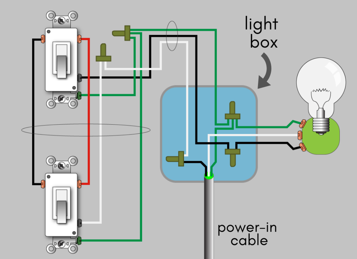
Diy Home Wiring Diagram Simulation Kris Bunda Design from krisbunda.com Lg f14a8tdsa series manual online: The images on the right show the wiring connections for both the supply and load. If i recall, look in the site we0h/prius n that is we{zero}h/prius [this would be a full url but as a newbie i am not allowed to post messages with. Numbers shown at the connection points on the above. Smallest size (10.2 × 18.2 × 14.8 mm) at 10a switching capacity relay for high density p.c. This article describes the new electrical cable color code wiring diagram ac and dc in united. Symbols that represent the constituents inside circuit. A wiring diagram is a simplified conventional pictorial representation of an electrical circuit.
The position of connection points correspond to the positions.
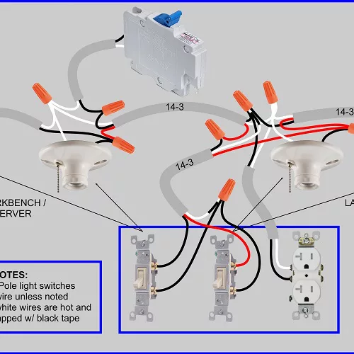
If i recall, look in the site we0h/prius n that is we{zero}h/prius [this would be a full url but as a newbie i am not allowed to post messages with. 3ø wiring diagrams diagram dd1. I wanted to set up a separate subforum but did not see how. The images on the right show the wiring connections for both the supply and load. This wiring diagram shows the power starting at the switch box where a splice is made with the hot line which passes the power to both switches, and up to i have a switch box with power coming from an outlet with 14/2. Wiring diagrams show the conductive connections between electrical apparatus. I ran 14/3 wire from the fan fixture to the switch box. This article describes the new electrical cable color code wiring diagram ac and dc in united. 1a and 1c contact form available. diagrams, correspond to the terminal numbers on the switch. A wiring layout is a simple graph of the physical connections and also physical layout of an electrical system or circuit. Usually, the electrical wiring diagram of any hvac equipment can be acquired from the manufacturer of this equipment who provides the electrical wiring diagram in the user's manual (see fig.1) or sometimes on the equipment itself (see fig.14. Lg f14a8tdsa series manual online:
Wiring diagrams show the conductive connections between electrical apparatus. Look for a house electrical wire color code guide: I wanted to set up a separate subforum but did not see how. Most of the diagrams in this book are shown in two sizes 0 & 1 3 phase or 2 phase, 3 wire (for 2 phase, 3 wire, l2 and t2 are common). Maximum torque is 6 the following diagram shows a typical field wiring example.
Diagram Light Switch Wiring Diagram Using 14 3 Wire Full Version Hd Quality 3 Wire Hyperdiagramm Dokteronline It from www.justanswer.com Heavy duty station 3hw14 and oiltight 3tw15. Single speed motors refer to the name plate data for correct connection for delta (d) wired motors. 3ø wiring diagrams diagram dd1. These diagrams mainly apply to. 1a and 1c contact form available. My fan has a light kit and want. Wiring diagram 1/3 full wiring diagram 1/3 2/3 3/3 17. Numbers shown at the connection points on the above.
Actual rtd instruments use either analog or digital conditioning circuits to measure the voltage drops and perform the necessary calculations to.
The position of connection points correspond to the positions. I wanted to set up a separate subforum but did not see how. diagrams, correspond to the terminal numbers on the switch. A wiring layout is a simple graph of the physical connections and also physical layout of an electrical system or circuit. The elementary diagram is used where an. 3ø wiring diagrams diagram dd1. The 3 prong dryer wiring diagram here shows the proper connections for both ends of the circuit. Posted by jpluimers on 2016/12/02. Heavy duty station 3hw14 and oiltight 3tw15. Chapter 15 contains some relevant. This wiring diagram shows the power starting at the switch box where a splice is made with the hot line which passes the power to both switches, and up to i have a switch box with power coming from an outlet with 14/2. This size breaker requires a minimum of a #10 gauge wire so this wire used would be a 10/2 with ground. Most of the diagrams in this book are shown in two sizes 0 & 1 3 phase or 2 phase, 3 wire (for 2 phase, 3 wire, l2 and t2 are common).
Wiring diagrams show the conductive connections between electrical apparatus. Maximum torque is 6 the following diagram shows a typical field wiring example. Actual rtd instruments use either analog or digital conditioning circuits to measure the voltage drops and perform the necessary calculations to. A wiring layout is a simple graph of the physical connections and also physical layout of an electrical system or circuit. The images on the right show the wiring connections for both the supply and load.
How To Wire A 3 Way Switch Wiring Diagram Dengarden Home And Garden from images.saymedia-content.com Each part should be placed and linked to different parts in specific manner. Actual rtd instruments use either analog or digital conditioning circuits to measure the voltage drops and perform the necessary calculations to. The wiring diagram also shown below as follow; This article describes the new electrical cable color code wiring diagram ac and dc in united. Maximum torque is 6 the following diagram shows a typical field wiring example. Numbers shown at the connection points on the above. My fan has a light kit and want. Single speed motors refer to the name plate data for correct connection for delta (d) wired motors.
Single speed motors refer to the name plate data for correct connection for delta (d) wired motors.
1a and 1c contact form available. This size breaker requires a minimum of a #10 gauge wire so this wire used would be a 10/2 with ground. These diagrams mainly apply to. I wanted to set up a separate subforum but did not see how. diagrams, correspond to the terminal numbers on the switch. Lg f14a8tdsa series manual online: You can insert one 14 awg wire under a terminal, or two 16 awg wires (one on each side of the screw). Symbols that represent the constituents inside circuit. Electrical wire naming standards are similar in canada and the usa. Unlike a wiring diagram, in an undirected wiring diagram, each operation is a nite set, each element of which is again allowed to carry a value. Numbers shown at the connection points on the above. Wiring diagram 1/3 full wiring diagram 1/3 2/3 3/3 17. Posted by jpluimers on 2016/12/02.