Home
› Wiring Schematic Diagram Symbol / Wiring Diagram - Everything You Need to Know About Wiring Diagram / Icons that represent the components in the circuit and also lines that represent the connections between them.
Wiring Schematic Diagram Symbol / Wiring Diagram - Everything You Need to Know About Wiring Diagram / Icons that represent the components in the circuit and also lines that represent the connections between them.
Wiring Schematic Diagram Symbol / Wiring Diagram - Everything You Need to Know About Wiring Diagram / Icons that represent the components in the circuit and also lines that represent the connections between them.. The diagram offers visual representation of an electric structure. Electronics symbols for schematics and wiring diagrams are mostly universal with a few of the symbols that may look different if reading other types of a schematic will help you to troubleshoot electrical circuits. The standard electrical symbols are smart industrial standard and vector based for electrical schematic diagrams. Limit switch legend aov schematic (with block included) wiring (or connection) diagram wiring (or connection) diagram tray & conduit layout drawing embedded conduit. Inspirational house wiring plan drawing • electrical outlet symbol 2018.
It covers circuit symbols such as resistors, capacitors, inductors, wires, ground, motors, batteries, electrolytic capacitors, lamps & lightbulbs, diodes, leds or light emitting diodes, solar cells, transformers, voltmeters crash course on how to read electrical schematics. A wiring diagram is a type of schematic that uses abstract pictorial symbols to show all the interconnections of components in a system. Limit switch legend aov schematic (with block included) wiring (or connection) diagram wiring (or connection) diagram tray & conduit layout drawing embedded conduit. Symbols that represent the components in the circuit, and lines that represent the connections between them. Nets are represented as lines between component terminals.
DIAGRAM Ladder Logic Diagram Symbols FULL Version HD Quality Diagram Symbols - BPMDIAGRAMS ... from www.conceptdraw.com If you are fixing, repairing, or troubleshooting an appliance, use the wiring diagram. As your basic vehicle wiring diagrams symbols feel free to get familiar with these symbols until you become used to it when you see it in any auto wiring diagram. The detail used for these symbols will vary when used in system diagrams. Type of wiring diagram wiring diagram vs schematic diagram how to read a wiring diagram: Wiring diagrams this is not an automated service. A 'blob' should be drawn where wires are connected (joined), but it is sometimes omitted. Symbols that represent the components in the circuit, and lines that represent the connections between them. Here is the wiring symbol legend, which is a detailed documentation of open an wiring diagram example or a blank drawing page.
Schematics using international symbols may instead use a featureless rectangle, instead of the squiggles.
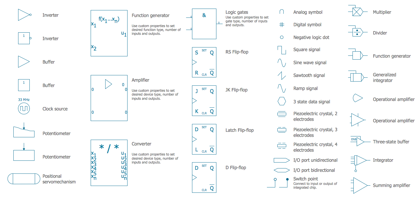
Icons that represent the components in the circuit and also lines that represent the connections between them. Circuit symbols are used in circuit diagrams (schematics) to represent electronic components. 01_b_r03 electrical basics drawing index. Type of wiring diagram wiring diagram vs schematic diagram how to read a wiring diagram: An electronic symbol is a pictogram used to represent various electrical and electronic devices or functions, such as wires, batteries, resistors, and transistors. Switch symbols and relay symbols. It covers circuit symbols such as resistors, capacitors, inductors, wires, ground, motors, batteries, electrolytic capacitors, lamps & lightbulbs, diodes, leds or light emitting diodes, solar cells, transformers, voltmeters crash course on how to read electrical schematics. They are wiring, schematic, and pictorial diagrams. Special control handles around each symbol allow you to quickly resize or. Circuit diagram symbols zen electric ~ wiring diagram components, size: Through schematic symbols you can also visualize analyze a circuit and how it works. All circuit symbols are in standard format and can be used for drawing schematic circuit diagram and layout. Symbols that represent the components in the circuit, and lines that represent the connections between them.
A 'blob' should be drawn where wires are connected (joined), but it is sometimes omitted. A wiring diagram is a simplified conventional pictorial representation of an electrical circuit. Normally automotive wiring diagram symbols refers to electrical schematic or circuits diagram. The standard electrical symbols are smart industrial standard and vector based for electrical schematic diagrams. Electrical symbols and electronic circuit symbols are used for drawing schematic diagram.
Wiring Diagram Symbols | Page 2 | DIYnot Forums from www.diynot.com A wiring diagram usually gives instruction not quite the relative point and promise of devices and terminals on the devices, to assist in building or servicing the device. Schematics using international symbols may instead use a featureless rectangle, instead of the squiggles. A the connecting leads or pins of a component in a. Normally automotive wiring diagram symbols refers to electrical schematic or circuits diagram. Switch symbols and relay symbols. Inspirational house wiring plan drawing • electrical outlet symbol 2018. They only provide general information and. It covers circuit symbols such as resistors, capacitors, inductors, wires, ground, motors, batteries, electrolytic capacitors, lamps & lightbulbs, diodes, leds or light emitting diodes, solar cells, transformers, voltmeters crash course on how to read electrical schematics.
As you enter into the workspace of edrawmax, you can drag and drop the.
They only provide general information and. Thus in circuit diagrams and schematics, graphical symbols identify and represent electrical and electronic devices and show how they are electrically connected together while drawing lines between them represents the wires or component leads. Schematics using international symbols may instead use a featureless rectangle, instead of the squiggles. Symbols that represent the components in the circuit, and lines that represent the connections between them. A 'blob' should be drawn where wires are connected (joined), but it is sometimes omitted. The detail used for these symbols will vary when used in system diagrams. It covers circuit symbols such as resistors, capacitors, inductors, wires, ground, motors, batteries, electrolytic capacitors, lamps & lightbulbs, diodes, leds or light emitting diodes, solar cells, transformers, voltmeters crash course on how to read electrical schematics. Here is the wiring symbol legend, which is a detailed documentation of open an wiring diagram example or a blank drawing page. Wiring diagrams are made up of two things: The standard electrical symbols are smart industrial standard and vector based for electrical schematic diagrams. Complete circuit symbols of electronic components. Circuit symbols are used in circuit diagrams (schematics) to represent electronic components. All circuit symbols are in standard format and can be used for drawing schematic circuit diagram and layout.
If you are fixing, repairing, or troubleshooting an appliance, use the wiring diagram. As your basic vehicle wiring diagrams symbols feel free to get familiar with these symbols until you become used to it when you see it in any auto wiring diagram. At this time were pleased to declare we have discovered an awfully interesting niche to be reviewed truly, we have been noticed that control wiring diagram symbols is being one of the most popular field at this moment. 800 x 600 px, source: There are three ways to show electrical circuits.
Symboles électriques pour schémas électriques | Lucidchart from d2slcw3kip6qmk.cloudfront.net Wiring diagrams this is not an automated service. Symbols you should know wiring diagram examples schematic diagrams show the circuit flow with its impression rather than a genuine representation. Wiring diagrams should identify all equipment parts, devices. Note that diodes force electrical currents in a single direction which is why the symbol resembles an arrow. A 'blob' should be drawn where wires are connected (joined), but it is sometimes omitted. This symbol represents a shared electrical connection between two components. Unlike a schematic diagram, which can be thought of as a conceptual drawing, the wiring diagram is designed for end users and installers who focus on making connections and troubleshooting components. A wiring diagram is a simplified conventional pictorial representation of an electrical circuit.
Circuit diagram symbols zen electric ~ wiring diagram components, size:
Electronics symbols for schematics and wiring diagrams are mostly universal with a few of the symbols that may look different if reading other types of schematics. Dc schematics, often referred to as elementary wiring diagrams, are the particular schematics that depict the dc system and usually show the care must be taken to appreciate the difference between the black triangle symbol used to indicate transitions and the black triangle symbol used in the lower. Complete circuit symbols of electronic components. Schematic nets tell you how components are wired together in a circuit. Circuit diagram symbols zen electric ~ wiring diagram components, size: At this time were pleased to declare we have discovered an awfully interesting niche to be reviewed truly, we have been noticed that control wiring diagram symbols is being one of the most popular field at this moment. There are three ways to show electrical circuits. Unlike a schematic diagram, which can be thought of as a conceptual drawing, the wiring diagram is designed for end users and installers who focus on making connections and troubleshooting components. Craftsman riding mower electrical diagram. Wiring schematic symbols chart roadmaps and wiring diagrams have a great deal in common not provide a legend on the bottom of the circuit diagram wiring schematic symbols chart in fact ada wrote about the possibility of computers using numbers as symbols to represent things like musical. Note that diodes force electrical currents in a single direction which is why the symbol resembles an arrow. Electrical symbols and electronic circuit symbols are used for drawing schematic diagram. In electronic circuits, there are many electronic symbols that are used to represent or identify a basic electronic or electrical device.