Home
› Ka3525 Sg3525 Inverter Circuit Diagram / 12V to +/- 30V DC to DC Inverter : Electrical characteristics (v# i = 20 v, and over operating temperature, unless otherwise specified).
Ka3525 Sg3525 Inverter Circuit Diagram / 12V to +/- 30V DC to DC Inverter : Electrical characteristics (v# i = 20 v, and over operating temperature, unless otherwise specified).
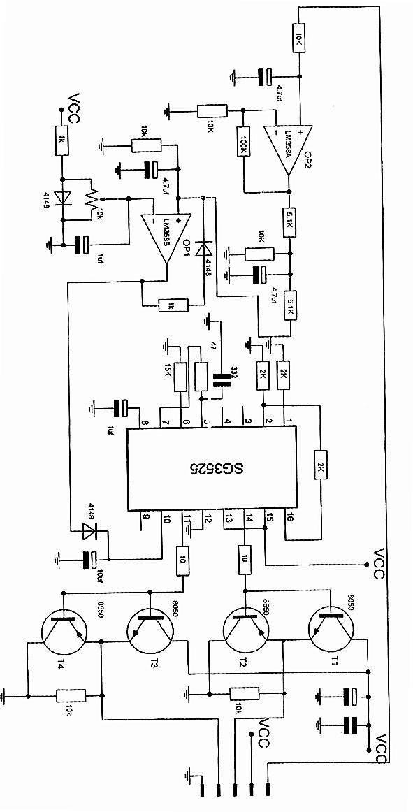
Ka3525 Sg3525 Inverter Circuit Diagram / 12V to +/- 30V DC to DC Inverter : Electrical characteristics (v# i = 20 v, and over operating temperature, unless otherwise specified).. Hi, in today's video i'll show you how to make a regulated power inverter with the popular sg3525 or uc3525 pwm ic. There are numerous pwm controllers available that make the use and application of pwm quite easy. Schematic diagram of the inverter exhibits the fig.1. Electrical characteristics (v# i = 20 v, and over operating temperature, unless otherwise specified). Inverter ka3525 sg3525 totem drive board empty pcb premium glass fiber plate.
Sg3525 inverter circuit which can be configured with the the above discussed full bridge network. Probably the inverter can power up by. This design is actually an universal design which may be implemented for upgrading all. Activating this circuit by applying a positive signal on pin 10 performs two functions: Make simple 555 inverter circuit using mosfet 3 high power sg3525 pure sinewave circuits pwm.
Sg3525 Inverter Circuit Pcb : Generic Sg3525 Ka3525 Driver Board Inverter Drive Board Has ... from img.alicdn.com Latch is immediately set providing the fastest turn−off signal to the outputs; Pwm is used in all sorts of power control and converter circuits. Activating this circuit by applying a positive signal on pin 10 performs two functions: Probably the inverter can power up by. Hi, in today's video i'll show you how to make a regulated power inverter with the popular sg3525 or uc3525 pwm ic. Circuit diagrams of example below show the circuit diagram of sg3525 which generates two inverted inverter circuit diagram example. High power inverter circuit diagram see here for more information. That could be available in all electronics shops with the cheapest price.
There are numerous pwm controllers available that make the use and application of pwm quite easy.
This design is actually an universal design which may be implemented for upgrading all square wave inverters into sinewave inverters. Parameter supply voltage collector supply voltage output current, sink or source reference output. Keep reading if you want to know about inverter circuit using sg3525 ic. The sg 3525 ic is a pwm producing ic. Probably the inverter can power up by. Electrical characteristics (v# i = 20 v, and over operating temperature, unless otherwise specified). This design is actually an universal design which may be implemented for upgrading all. This article is all about sg3525 inverter circuit and sg3525 pinout and its ic number. This is a pin configuration diagram and the functionality of each pin is provided in the next section. Pwm is used in all sorts of power control and converter circuits. The output can be smoothly adjusted from. A typical circuit design for converting the sg3525 waveform into a pure sinewave waveform is shown below. Hi, in today's video i'll show you how to make a regulated power inverter with the popular sg3525 or uc3525 pwm ic.
Hi, in today's video i'll show you how to make a regulated power inverter with the popular sg3525 or uc3525 pwm ic. Sg3525 inverter circuit which can be configured with the the above discussed full bridge network. On the contrary circuit shut down when connected the any find more other pcb & pcba information about sg3525 ka3525 driver board inverter drive board has independent overload and short circuit. The on−chip +5.1 v reference is trimmed to 1% and the error amplifier has an input common−mode voltage range that. The output can be smoothly adjusted from.
sg3525 lm358 inverter circuit - SHEMS from stone.umelecforum.ru Voltage 220vac parts list for the 220v inverter circuit using sg3525 and output voltage correction feature. The driver board circuit and the pcb layout i am given in the youtube video. On the contrary circuit shut down when connected the any find more other pcb & pcba information about sg3525 ka3525 driver board inverter drive board has independent overload and short circuit. There are numerous pwm controllers available that make the use and application of pwm quite easy. Sg3525 inverter circuit which can be configured with the the above discussed full bridge network. The proposed sg3535 inverter circuit with output correction has been tested practically and worked well with outstanding accuracy. Circuit diagrams of example below show the circuit diagram of sg3525 which generates two inverted inverter circuit diagram example. Sg3525 circuits sg3525 projects sg3525 pulse width modulator pwm control integrated, can be used for the control of all kinds of switched power supply.
Make simple 555 inverter circuit using mosfet 3 high power sg3525 pure sinewave circuits pwm.
The output can be smoothly adjusted from. A typical circuit design for converting the sg3525 waveform into a pure sinewave waveform is shown below. Voltage 220vac parts list for the 220v inverter circuit using sg3525 and output voltage correction feature. Latch is immediately set providing the fastest turn−off signal to the outputs; Sg3525 circuits sg3525 projects sg3525 pulse width modulator pwm control integrated, can be used for the control of all kinds of switched power supply. Keep reading if you want to know about inverter circuit using sg3525 ic. There are numerous pwm controllers available that make the use and application of pwm quite easy. Pulse width modulator control circuits, sg3525 datasheet, sg3525 circuit, sg3525 data sheet : The ka3525a is a monolithic integrated circuit that includes all of the control circuits necessary for a pulse width modulating regulator. Step by step sg3525 inverter circuit diagram and sg3525 pinout. The following image shows an example inverter circuit using the ic sg3525, you can observe that the output mosfet stage is missing in the diagram, and only the output open pinouts can. This article is all about sg3525 inverter circuit and sg3525 pinout and its ic number. Circuit diagrams of example below show the circuit diagram of sg3525 which generates two inverted inverter circuit diagram example.
This is a pin configuration diagram and the functionality of each pin is provided in the next section. Voltage 220vac parts list for the 220v inverter circuit using sg3525 and output voltage correction feature. Motorola, alldatasheet, datasheet, datasheet search site for electronic components and semiconductors, integrated circuits, diodes, triacs, and other semiconductors. Step by step sg3525 inverter circuit diagram and sg3525 pinout. Sg3525 circuits sg3525 projects sg3525 pulse width modulator pwm control integrated, can be used for the control of all kinds of switched power supply.
welding inverter circuit using ka3525 - SHEMS from stone.umelecforum.ru The driver board circuit and the pcb layout i am given in the youtube video. The ka3525a is a monolithic integrated circuit that includes all of the control circuits necessary for a pulse width modulating regulator. Ka3525a smps controller www.fairchildsemi.com features • 5v ±1% reference • oscillator sync termin. Make simple 555 inverter circuit using mosfet 3 high power sg3525 pure sinewave circuits pwm. An additional clamping circuit tend to be components d8, r6, pr1, us2, r7, r8, and c4 the sg3525a pulse width modulator control circuit offers improved performance and lower external parts count when implemented for controlling all. Motorola, alldatasheet, datasheet, datasheet search site for electronic components and semiconductors, integrated circuits, diodes, triacs, and other semiconductors. Step by step sg3525 inverter circuit diagram and sg3525 pinout. Pulse width modulator control circuits, sg3525 datasheet, sg3525 circuit, sg3525 data sheet :
Make simple 555 inverter circuit using mosfet 3 high power sg3525 pure sinewave circuits pwm.
Step by step sg3525 inverter circuit diagram and sg3525 pinout. Keep reading if you want to know about inverter circuit using sg3525 ic. Sg3525 inverter circuit which can be configured with the the above discussed full bridge network. This design is actually an universal design which may be implemented for upgrading all. Schematic diagram of the inverter exhibits the fig.1. Sg3525 circuits sg3525 projects sg3525 pulse width modulator pwm control integrated, can be used for the control of all kinds of switched power supply. Circuit diagrams of example below show the circuit diagram of sg3525 which generates two inverted inverter circuit diagram example. The on−chip +5.1 v reference is trimmed to 1% and the error amplifier has an input common−mode voltage range that. A typical circuit design for converting the sg3525 waveform into a pure sinewave waveform is shown below. Motorola, alldatasheet, datasheet, datasheet search site for electronic components and semiconductors, integrated circuits, diodes, triacs, and other semiconductors. Electrical characteristics (v# i = 20 v, and over operating temperature, unless otherwise specified). On the contrary circuit shut down when connected the any find more other pcb & pcba information about sg3525 ka3525 driver board inverter drive board has independent overload and short circuit. This driver board is enough for the power inverter construction.