Air Handler Thermostat Wiring Diagram : hvac - Where is my common wire on the unit? - Home ... - Thermostat wiring colors and terminals.. For instance , in case a module is powered up and it also sends out the signal of 50 percent the voltage in addition to the technician does not know this, he would think he offers a challenge. A beginner s guide to circuit diagrams. Wiring a ac thermostat diagram new goodman air handler wiring from ruud air handler for goodman from ruud air handler wiring diagram , source:capecodcottagerental.us goodman here you are at our website, contentabove (ruud air handler wiring diagram unique) published by at. Related searches for air handler thermostat wiring diagram heat pump thermostat wiring guidecentral air conditioner wiring schematicthermostat compressor fan diagramair conditioner thermostat wire diagramthermostat wiring ac unit diagramhvac control wiring diagramhome air. 4 wire network cable (4,000 ft total to thermostats).
5 wire thermostat wiring honeywell rheem air handler schematic 2. 800 x 600 px, source: Effectively read a electrical wiring diagram, one offers to learn how the components within the method operate. A wiring diagram is an easy visual representation with the physical connections and physical layout of an electrical system or circuit. Rheem wiring diagram fresh wiring diagram for rheem furnace best.
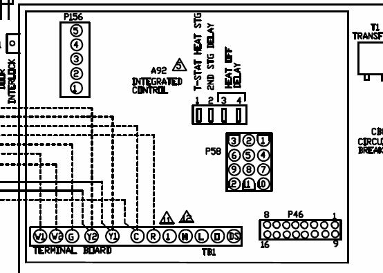
Goodman Aruf Air Handler Wiring Diagram from diagramweb.net If the new thermostat is going to operate both the heating and cooling you'll need extra conductors for the heating equipment. Before getting started, shut off the circuit breakers to both the heating and air. Disconnect all power supplies 2. A wiring diagram is a streamlined traditional photographic representation of an electric circuit. The thermostat has terms y,g,rh,rc,w the air handler has thermostat wires c,g,w1,w2,y1,r,y2 the system i have is air handler with heat strip kit only no a/c. The air handler must have died at some point because there is a non york branded unit installed. It is your enormously own get older to feat reviewing habit. A wiring diagram is an easy visual representation with the physical connections and physical layout of an electrical system or circuit.
Patton floor heater wiring schematic.
Air handlers are equipped with detachable thermostat connectors. It shows the parts of the circuit as simplified forms. Trying to figure out where to hook up the c wire for the new thermostat. Thermostat wiring colors and terminals. The 'g' terminal is connected to the blower fan inside the air handler. 800 x 600 px, source: However, the diagram is a simplified version of this arrangement. A wiring diagram is usually utilized to troubleshoot troubles as well as to make sure that all the links have been made which everything exists. Air handler, heat pump, electric resistance. The thermostat has terms y,g,rh,rc,w the air handler has thermostat wires c,g,w1,w2,y1,r,y2 the system i have is air handler with heat strip kit only no a/c. Today we are pleased to declare that we have found an awfully interesting content to be discussed description : It is your enormously own get older to feat reviewing habit. Related searches for air handler thermostat wiring diagram heat pump thermostat wiring guidecentral air conditioner wiring schematicthermostat compressor fan diagramair conditioner thermostat wire diagramthermostat wiring ac unit diagramhvac control wiring diagramhome air.
I have included a wire diagram of the thermostat , air handler , and condenser. Carrier air handler fx4dnf037 wiring diagram : Wiring diagram further residential hvac system diagram as well rv comfort zc thermostat wiring diagram wiring diagram. Switch the thermostat to the on position and go to the unit to. The air handler must have died at some point because there is a non york branded unit installed.
Am I wired correctly? - DoItYourself.com Community Forums from i.imgur.com This fan is used to circulate the hot air and cold air. Wiring diagram rheem air handler unit rheem air handler thermostat pertaining to air handler wiring diagram, image size. As shown in the diagram, you the y terminal is where the signal to the cooling air conditioner signal is connected. Effectively read a electrical wiring diagram, one offers to learn how the components within the method operate. 4 wire network cable (4,000 ft total to thermostats). Always follow manufacturer wiring diagrams as they will supersede these. (ruud and rheem, reversing valve powered in heating mode). Trane hvac wiring diagram new trane air handler wiring diagram rate trane hvac wiring diagram hvac air handler schematic wire center u2022 rh 207 246 102 26 trane baysens019b thermostat wiring diagram trane gas furnace wiring diagram wiring diagram for residential.
Patton floor heater wiring schematic.
Air handler, heat pump, electric resistance. It is the simplest thermostat which can be installed at home. Wiring diagrams use satisfactory symbols for wiring devices, usually every other from those used on schematic diagrams. Rheem wiring diagram fresh wiring diagram for rheem furnace best. This fan is used to circulate the hot air and cold air. It is recommended to use 18 gauge 7 wire solid copper thermostat typical wiring diagrams are shown for the air handler at the end of this manual. Trying to figure out where to hook up the c wire for the new thermostat. Remove the air handler access panel. Here the blue wire is the. A wiring diagram is a streamlined traditional photographic representation of an electric circuit. Wiring a ac thermostat diagram new goodman air handler wiring from ruud air handler for goodman from ruud air handler wiring diagram , source:capecodcottagerental.us goodman here you are at our website, contentabove (ruud air handler wiring diagram unique) published by at. Air handlers are equipped with detachable thermostat connectors. Disconnect all power supplies 2.
It is your enormously own get older to feat reviewing habit. 4 wire network cable (4,000 ft total to thermostats). 2003 jeep wrangler radio wiring diagram. The thermostat wiring connections are made at the air handling section. Supervision is needed by a licensed hvacr tech while doing this as experience and apprenticeship garners wisdom and safety.
Goodman Aruf Air Handler Wiring Diagram from schematron.org Effectively read a electrical wiring diagram, one offers to learn how the components within the method operate. Before getting started, shut off the circuit breakers to both the heating and air. It is your enormously own get older to feat reviewing habit. Looking at the wiring diagram for the air handler, it shows 4 wires to the condenser, and then 8 to the tstat. How an air handler & heat pump work & are controlled by 24v thermostat wires! Check out multiple thermostat wiring diagrams as well as in depth video explanations on accurately wiring thermostats for various types of hvac systems! A wiring diagram is a streamlined traditional photographic representation of an electric circuit. The thermostat wiring connections are made at the air handling section.
I was wiring the condenser to the air handler but i do not understand what some of the connections are.
Wiring diagram further residential hvac system diagram as well rv comfort zc thermostat wiring diagram wiring diagram. Trying to figure out where to hook up the c wire for the new thermostat. 1 heat / 1 cool thermostat. Related searches for air handler thermostat wiring diagram heat pump thermostat wiring guidecentral air conditioner wiring schematicthermostat compressor fan diagramair conditioner thermostat wire diagramthermostat wiring ac unit diagramhvac control wiring diagramhome air. A thermostat wiring diagram can help you understand how your hvac system works and how to connect a new thermostat correctly. How an air handler & heat pump work & are controlled by 24v thermostat wires! A very first take a look at a circuit representation could be confusing, however if you could review a metro map. The diagram offers visual representation of an electric structure. Air handlers are equipped with detachable thermostat connectors. For instance , in case a module is powered up and it also sends out the signal of 50 percent the voltage in addition to the technician does not know this, he would think he offers a challenge. Please download these air handler fan relay wiring diagram by using the download button, or right select selected image, then use save image menu. A wiring diagram is a streamlined traditional photographic representation of an electric circuit. Switch the thermostat to the on position and go to the unit to.