Home
› Trailer Wiring Diagram With Brakes : Trailer Wiring Diagrams North Texas Trailers Fort Worth - A wiring diagram is a kind of schematic which uses abstract pictorial symbols showing every one of the interconnections of components in a very system.
Trailer Wiring Diagram With Brakes : Trailer Wiring Diagrams North Texas Trailers Fort Worth - A wiring diagram is a kind of schematic which uses abstract pictorial symbols showing every one of the interconnections of components in a very system.
Trailer Wiring Diagram With Brakes : Trailer Wiring Diagrams North Texas Trailers Fort Worth - A wiring diagram is a kind of schematic which uses abstract pictorial symbols showing every one of the interconnections of components in a very system.. Ensure it is sealed off and cannot create a short circuit with any other wire or the chassis. Not just will it help you attain your… Search for wiring diagram trailer brakes on the new kensaq.com This is done by cutting the wire about half an inch back and attaching it to the shrink hose of the trailer. Elecbrakes must be connected to trailer wiring circuits as outlined in the wiring diagram.
Search for wiring trailer brakes diagram fast and save time This 7 pin trailer wiring diagram electric brakes model is more suitable for sophisticated trailers and rvs. Not just will it help you attain your… Installing new trailer brakes on a tanden axle trailer.when wiring my understanding is that the existing 7 pole wiring can be tapped into by running a two wire 12 guage section from brake to brake and then splicing into the existing 7 ptong and attaching the blue and whiteground wires.do i have to ground the white wire to the trailer ? The trailer wiring diagram shows this wire going to all the lights and brakes.
Trailer Wiring Chevrolet Forum Chevy Enthusiasts Forums from chevroletforum.com It also talks about electric brake controller.thanks for watching ! This car is designed not only to travel 1 location to another but also to take heavy loads. The service brake circuit must be disconnected from an existing trailer plug. White pin for the ground. A wiring diagram is an normal photographic representation of a complicated electric circuit. Search for wiring trailer brakes diagram fast and save time Search for wiring diagram trailer brakes on the new kensaq.com The trailer wiring diagram shows this wire going to all the lights and brakes.
You must heat the surface with a heat gun and then drill a hole in the hose.
Find wiring trailer brakes diagram here with us! Narva 7 and 12 pin trailer connectors comply with all relevant adrs. Elecbrakes must be connected to trailer wiring circuits as outlined in the wiring diagram. As the name implies, they use four wires to carry out the vital lighting functions. This short video is about trailer brakes, electric brakes and wiring. A wiring diagram is a streamlined traditional pictorial representation of an electrical circuit. This report will be discussing 6 pin trailer wiring diagram with brakes.which are the benefits of understanding these understanding? It reveals the parts of the circuit as streamlined forms, as well as the power and signal connections in between the gadgets. Ensure it is sealed off and cannot create a short circuit with any other wire or the chassis. White pin for the ground. This voyager trailer brake controller wiring diagram model is much more suitable for sophisticated trailers and rvs. Related post to trailer brake wiring diagram. As a professional rv transporter i have seen to many trucks wired with those 2 wires to small and cause a fire from overheating.
As the name implies, they use four wires to carry out the vital lighting functions. This makes the process of assembling circuit easier. You must heat the surface with a heat gun and then drill a hole in the hose. This is done by cutting the wire about half an inch back and attaching it to the shrink hose of the trailer. 10 best trailer brake controllers.
5 Flat Trailer Wiring Harness 33 Load Rite Trailers from www.loadrite.com This is done by cutting the wire about half an inch back and attaching it to the shrink hose of the trailer. It reveals the parts of the circuit as streamlined forms, as well as the power and signal connections in between the gadgets. White pin for the ground. A wiring diagram is a streamlined traditional pictorial representation of an electrical circuit. However, the diagram is a simplified variant of this arrangement. This 7 pin trailer wiring diagram electric brakes model is more suitable for sophisticated trailers and rvs. This guide will be talking trailer breakaway wiring diagram.which are the advantages of knowing these understanding? Elecbrakes must be connected to trailer wiring circuits as outlined in the wiring diagram.
The service brake circuit must be disconnected from an existing trailer plug.
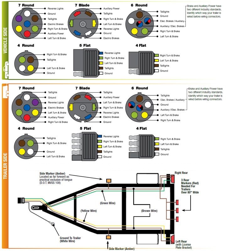
Trailer wiring diagrams trailer wiring connectors various connectors are available from four to seven pins that allow for the transfer of power for the lighting as well as auxiliary functions such as an electric trailer brake controller, backup lights, or a 12v power supply for a winch or interior trailer lights. A wiring diagram is an ordinary pictorial depiction of a intricate electrical circuit. 10 best trailer brake controllers. The four wires control the turn signals, brake lights and taillights or running lights. This 7 pin trailer wiring diagram electric brakes model is more suitable for sophisticated trailers and rvs. This makes the process of assembling circuit easier. This wiring electric trailer brakes diagram model is more acceptable for sophisticated trailers and rvs. However, the diagram is a simplified variant of this arrangement. Narva 7 and 12 pin trailer connectors comply with all relevant adrs. They also provide a wire for a ground connection. Assortment of electric trailer brake wiring schematic. Related post to trailer brake wiring diagram. A wiring diagram is a streamlined conventional pictorial representation of an electric circuit.
A wiring diagram is an ordinary pictorial depiction of a intricate electrical circuit. Ensure it is sealed off and cannot create a short circuit with any other wire or the chassis. Wiring diagram trailer plugs and sockets. This guide will be talking trailer breakaway wiring diagram.which are the advantages of knowing these understanding? 10 best trailer brake controllers.
2007 F150 Quick Trailer Wiring Install F150online Forums from www.elite-computer.net A wiring diagram is a kind of schematic which uses abstract pictorial symbols showing every one of the interconnections of components in a very system. This makes the process of assembling circuit easier. A wiring diagram is an ordinary pictorial depiction of a intricate electrical circuit. 7 way plug wiring diagram standard wiring* post purpose wire color tm park light green (+) battery feed black rt right turn/brake light brown lt left turn/brake light red s trailer electric brakes blue gd ground white a accessory yellow this is the most common (standard) wiring scheme for rv plugs and the one used by major auto manufacturers today. Trailer wiring diagrams trailer wiring connectors various connectors are available from four to seven pins that allow for the transfer of power for the lighting as well as auxiliary functions such as an electric trailer brake controller, backup lights, or a 12v power supply for a winch or interior trailer lights. It also talks about electric brake controller.thanks for watching ! This short video is about trailer brakes, electric brakes and wiring. This 7 pin trailer wiring diagram electric brakes model is more suitable for sophisticated trailers and rvs.
It reveals the parts of the circuit as streamlined forms, as well as the power and signal connections in between the gadgets.
Elecbrakes must be connected to trailer wiring circuits as outlined in the wiring diagram. Assortment of electric trailer brake wiring schematic. A wiring diagram is a streamlined conventional pictorial representation of an electric circuit. 7 way plug wiring diagram standard wiring* post purpose wire color tm park light green (+) battery feed black rt right turn/brake light brown lt left turn/brake light red s trailer electric brakes blue gd ground white a accessory yellow this is the most common (standard) wiring scheme for rv plugs and the one used by major auto manufacturers today. Electric trailer brake wiring and parts diagrams click here to shop for electric trailer brakes and brake parts the two main types of electric brake assemblies for axles 7k and below are forward self adjusting (fsa) and manual adjusting. The trailer wiring diagram shows this wire going to all the lights and brakes. They also provide a wire for a ground connection. Installing new trailer brakes on a tanden axle trailer.when wiring my understanding is that the existing 7 pole wiring can be tapped into by running a two wire 12 guage section from brake to brake and then splicing into the existing 7 ptong and attaching the blue and whiteground wires.do i have to ground the white wire to the trailer ? This car is designed not only to travel 1 location to another but also to take heavy loads. White pin for the ground. This is done by cutting the wire about half an inch back and attaching it to the shrink hose of the trailer. A wiring diagram is a kind of schematic which uses abstract pictorial symbols showing every one of the interconnections of components in a very system. Find wiring trailer brakes diagram here with us!