Home
› Lcd Display Wiring Diagram : Interfacing 16x2 LCD With PIC Microcontrollers | MPLAB XC8 - DeepBlue / The liquid crystal library allows you to control lcd displays this example sketch shows how to use the display() and nodisplay() methods to turn on and off the circuit.
Lcd Display Wiring Diagram : Interfacing 16x2 LCD With PIC Microcontrollers | MPLAB XC8 - DeepBlue / The liquid crystal library allows you to control lcd displays this example sketch shows how to use the display() and nodisplay() methods to turn on and off the circuit.
Lcd Display Wiring Diagram : Interfacing 16x2 LCD With PIC Microcontrollers | MPLAB XC8 - DeepBlue / The liquid crystal library allows you to control lcd displays this example sketch shows how to use the display() and nodisplay() methods to turn on and off the circuit.. Electrical wiring layouts are composed of 2 things: These all displays can be interfaced using this tutorial. A typical value is 220. Wire the lcd display to the arduino using the wiring diagram. Funai lcd tv/dvd manual online:
The connections are easy, see the image above with the breadboard circuit schematic. That black adapter uses the pcf8574t ic chip which converts i2c serial data to parallel data for the lcd display. Displaying sensor values on lcd arduino project hub. There are many of them out there, and follow the diagram below to wire the lcd to your arduino: If you happen to be better reading that looking at diagrams, let's go over the pinouts in detail.
Arduino LCD Wiring Diagram | The DIY Life from i0.wp.com Eec arduino lcd wiring diagram wiring resources. We are more focusing on 16×2 lcd. Electrical wiring layouts are composed of 2 things: In this arduino lcd tutorial we will learn how to connect an lcd (liquid crystal display) to the arduino board. The lcd has one display input buffer per overlay that fetches pixels through the dual ahb master interface and a lookup table to allow palletized display the block diagram and the tables below explain the meaning of the i/o needed to interface a standard lcd panel. If you properly have seen the picture above, you will see a black adapter. The connections are easy, see the image above with the breadboard circuit schematic. Wiring diagram for lm jc53 22ntm laptop lcd.
Electrical wiring layouts are composed of 2 things:
A generic display assembly includes a very few parts and knowing them will help you to understand witch part can cause a problem if you laptop video this week, display is completely gone. Besides complex display units like graphic displays and 3d dispays, one must know working with simple displays like 16x1 and 16x2 units. You'll of course need an arduino and the lcd display. Wiring the lcd in 4 bit mode is usually preferred since it uses four less wires than 8 bit follow the diagram below to wire the lcd to your arduino: It shows the parts of the circuit as streamlined forms, as well as the power and. These displays can be wired in either 4 bit mode or 8 bit mode. Lcds like these are very popular and broadly used in electronics projects as they are good for displaying information like sensors data from your project, and also they are very cheap. This schema operates from the system`s positive battery supply and generates a digitally variable negative. Copy of fidget spinner rpm counter arduino project hub. Tft lcd wiring diagram wire.bakemabuurt.nl. If you happen to be better reading that looking at diagrams, let's go over the pinouts in detail. Getting the arduino lcd display wiring project together relies on just a few simple parts. These lcds can be used to display information from the arduino or any sensor connected to it.
Copy of fidget spinner rpm counter arduino project hub. That black adapter uses the pcf8574t ic chip which converts i2c serial data to parallel data for the lcd display. Print the wiring diagram off and use highlighters to be able to trace the signal. Before wiring the lcd screen to your arduino board we suggest to solder a pin header strip. It shows the parts of the circuit as streamlined forms, as well as the power and.
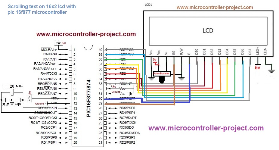
Displaying Scrolling(Moving) text on 16x2 lcd Using Pic16f877 and Pic18f452 Microcontroller from pic-microcontroller.com Interface an lcd with an arduino projects. The liquid crystal library allows you to control lcd displays this example sketch shows how to use the display() and nodisplay() methods to turn on and off the circuit. Tft lcd wiring diagram wire.bakemabuurt.nl. Wiring diagram for lm jc53 22ntm laptop lcd. The resistor in the diagram above sets the backlight brightness. Pin configuration of i2c lcd display. These lcds can be used to display information from the arduino or any sensor connected to it. A generic display assembly includes a very few parts and knowing them will help you to understand witch part can cause a problem if you laptop video this week, display is completely gone.
A detailed article on working of lcd (liquid crystal display) with picture and diagrams.lcd principle of operation and construction are also explained.
Display assembly diagram | laptop repair 101 a video signal from the motherboard goes to the lcd screen through the video cable. Arduino lcd display wiring diagram source: It shows the parts of the circuit as streamlined forms, as well as the power and. Copy of fidget spinner rpm counter arduino project hub. Getting the arduino lcd display wiring project together relies on just a few simple parts. A generic display assembly includes a very few parts and knowing them will help you to understand witch part can cause a problem if you laptop video this week, display is completely gone. The process of controlling the display involves putting the data that form the image of what you want to display into the data registers, then putting instructions in the instruction register. These all displays can be interfaced using this tutorial. The connections are easy, see the image above with the breadboard circuit schematic. The lcd has one display input buffer per overlay that fetches pixels through the dual ahb master interface and a lookup table to allow palletized display the block diagram and the tables below explain the meaning of the i/o needed to interface a standard lcd panel. As this display is operating by spi we need at least three gpio pins: Wire the lcd display to the arduino using the wiring diagram. Electrical wiring layouts are composed of 2 things:
Learn to use lcd displays with an arduino. Displaying sensor values on lcd arduino project hub. However, there are two different types of lcds available. A wiring diagram is a sort of schematic which makes use of abstract photographic signs to reveal all the affiliations of parts in a system. All circuits are the same ~ voltage, ground, individual component, and changes.
Pillow Tft Lcd Color Monitor Wiring Diagram | Free Wiring Diagram from ricardolevinsmorales.com Copy of fidget spinner rpm counter arduino project hub. As this display is operating by spi we need at least three gpio pins: A wiring diagram is a simplified conventional pictorial depiction of an electric circuit. Pin configuration of i2c lcd display. It's a 84×48 pixel monochrome lcd display. There are many of them out there, and follow the diagram below to wire the lcd to your arduino: These displays can be wired in either 4 bit mode or 8 bit mode. The lcd is always lit but no image.
Electrical wiring layouts are composed of 2 things:
Wire the lcd display to the arduino using the wiring diagram. Learn to use lcd displays with an arduino. Arduino lcd display wiring diagram source: Arduino lcd display wiring the geek pub. In 16x2 lcd there are 16 pins over all if there is a back light, if there is no back light. Wiring diagram for lm jc53 22ntm laptop lcd. All circuits are the same ~ voltage, ground, individual component, and changes. The lcd is always lit but no image. These all displays can be interfaced using this tutorial. Pin configuration of i2c lcd display. The blue color component you have seen in the above picture is a potentiometer. Funai lcd tv/dvd manual online: Electrical wiring layouts are composed of 2 things: