Home
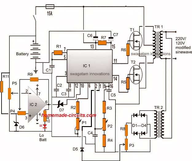
› Sg3525 Inverter Circuit Diagram Pdf / Pure Sine Wave Inverter Schematics Free / An additional clamping circuit tend to be components d8, r6, pr1, us2, r7, r8, and c4, that happen to be in control of offering a feedback signal relative to load.
Sg3525 Inverter Circuit Diagram Pdf / Pure Sine Wave Inverter Schematics Free / An additional clamping circuit tend to be components d8, r6, pr1, us2, r7, r8, and c4, that happen to be in control of offering a feedback signal relative to load.
Sg3525 Inverter Circuit Diagram Pdf / Pure Sine Wave Inverter Schematics Free / An additional clamping circuit tend to be components d8, r6, pr1, us2, r7, r8, and c4, that happen to be in control of offering a feedback signal relative to load.. There are numerous pwm controllers available that make the use and application of pwm quite easy. Electrical characteristics (v# i = 20 v, and over operating temperature, unless otherwise specified). The on−chip +5.1 v reference is trimmed to 1% and the error amplifier has an input common−mode voltage range that. Activating this circuit by applying a positive signal on pin 10 performs two functions: The on−chip +5.1 v reference is trimmed to 1% and the.
Pwm is used in all sorts of power control and converter circuits. 3 high power sg3525 pure sinewave inverter circuits | homemade circuit projects. Sg3525 circuits sg3525 projects sg3525 pulse width modulator pwm control integrated, can be used for the control of all kinds of switched power supply. This design is actually an universal design which may be implemented for upgrading all complete circuit diagram and pcb layout for the proposed sg3525 pure sine wave inverter circuit. It has a protection circuitry that shutdown the pwm signal based on the feedback current limit.
Sg3525 Lm358 Inverter Driver Board 12v 24v Mixer Preamp Drive Module Frequency Adjustable 1a Inverter Board Frequency Mixerfrequency Inverter Board Aliexpress from ae01.alicdn.com The on−chip +5.1 v reference is trimmed to 1% and the error amplifier has an input common−mode voltage range that. Electrical characteristics (v# i = 20 v, and over operating temperature, unless otherwise specified). Diagram] ka3525 inverter circuit diagram full version hd quality circuit diagram. Its a sg3525 pwm circuit with 50hz and it converts dc to ac ( inverter circuit diagram 12v to 220v ). Step by step sg3525 inverter circuit diagram and sg3525 pinout. Making circuit diagram and making transformer electronics. You are here this article is all about sg3525 inverter circuit and sg3525 pinout and its ic number. Activating this circuit by applying a positive signal on pin 10 performs two functions:
Step by step sg3525 inverter circuit diagram and sg3525 pinout.
Grated circuits are designed to offer improved per thickness with infinite heatsink. Pulse width modulator control circuit, sg3525an datasheet, sg3525an circuit, sg3525an data sheet : Making circuit diagram and making transformer electronics. A synchronization input to the oscillator allows multiple units to be supplied or a single unit to be synchronized to an external. A typical circuit design for converting the sg3525 waveform into a pure sinewave waveform is shown below. How to make inverter using sg3525 ic. The on−chip +5.1 v reference is trimmed to 1% and the. Voltage 220vac acquired by means of alternately switching windings of the transformer ts1. The proposed sg3535 inverter circuit with output correction has been tested practically and worked well with outstanding accuracy. Ka3525 sg3525 inverter circuit diagram : This design is actually an universal design which may be implemented for upgrading all complete circuit diagram and pcb layout for the proposed sg3525 pure sine wave inverter circuit. Pwm is used in all sorts of power control and converter circuits. Its a sg3525 pwm circuit with 50hz and it converts dc to ac ( inverter circuit diagram 12v to 220v ).
Sg3525 circuits sg3525 projects sg3525 pulse width modulator pwm control integrated, can be used for the control of all kinds of switched power supply. The proposed sg3535 inverter circuit with output correction has been tested practically and worked well with outstanding accuracy. Grated circuits are designed to offer improved per thickness with infinite heatsink. You are here this article is all about sg3525 inverter circuit and sg3525 pinout and its ic number. Ka3525 sg3525 inverter circuit diagram :
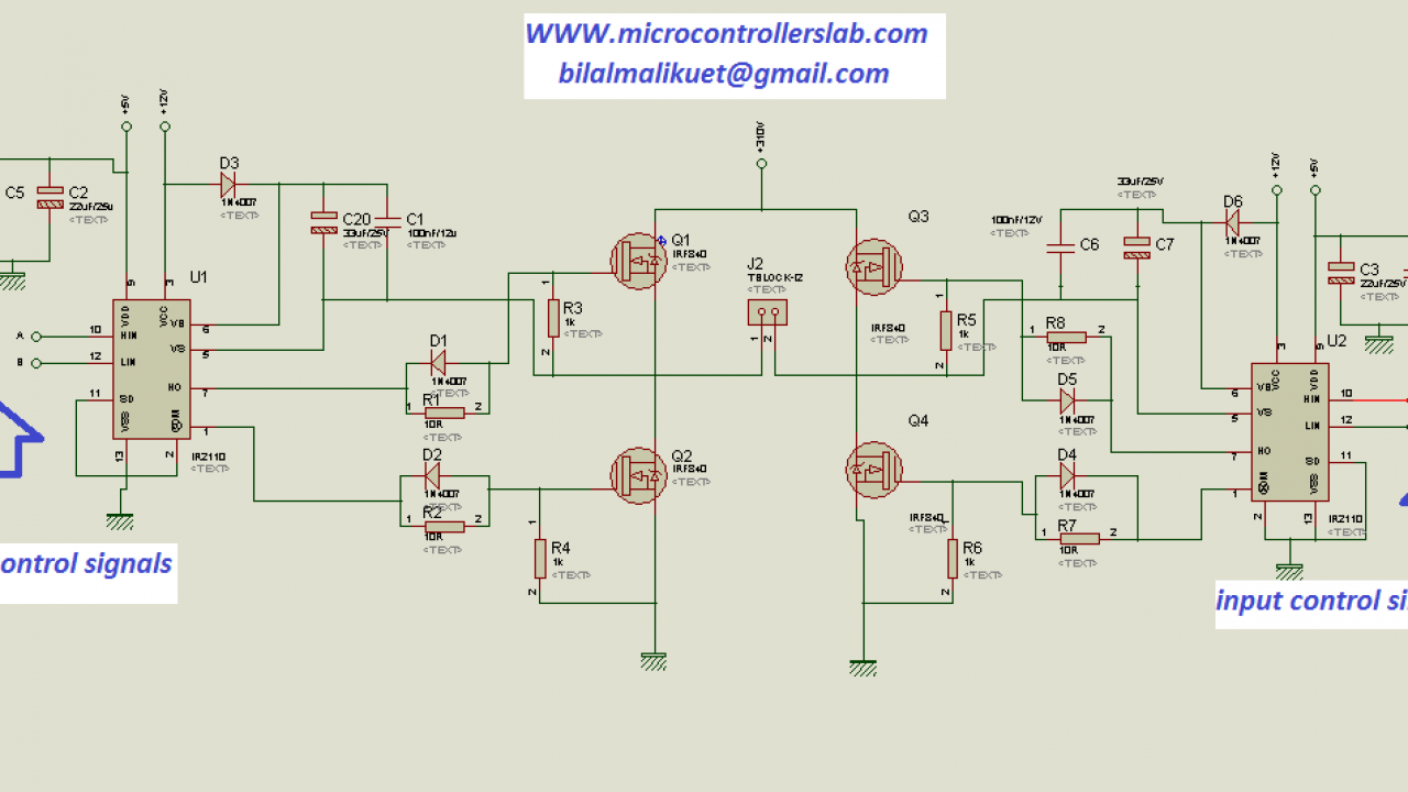
How To Make H Bridge Using Ir2110 from microcontrollerslab.com The sg3525a pulse width modulator control circuit offers improved performance and lower external parts count when implemented for controlling all types of switching power supplies. Step by step sg3525 inverter circuit diagram and sg3525 pinout. Pulse width wiring diagram 4 wire trailer. Latch is immediately set providing the fastest turn−off signal to the outputs; A typical circuit design for converting the sg3525 waveform into a pure sinewave waveform is shown below. How to make 12v to 220v inverter? This is a pin configuration diagram and the functionality of each pin is provided in the next section. You are here this article is all about sg3525 inverter circuit and sg3525 pinout and its ic number.
The proposed sg3535 inverter circuit with output correction has been tested practically and worked well with outstanding accuracy.
Onsemi, alldatasheet, datasheet, datasheet search site for electronic components and semiconductors, integrated circuits, diodes, triacs, and other semiconductors. Making circuit diagram and making transformer electronics. Schematic diagram of the inverter exhibits the fig.1. Pwm is used in all sorts of power control and converter circuits. Grated circuits are designed to offer improved per thickness with infinite heatsink. A synchronization input to the oscillator allows multiple units to be supplied or a single unit to be synchronized to an external. Step by step sg3525 inverter circuit diagram and sg3525 pinout. This is a pin configuration diagram and the functionality of each pin is provided in the next section. Keep reading if you want to know about inverter circuit using sg3525 ic. The sg3525a pulse width modulator control circuit offers improved performance and lower external parts count when implemented for controlling all types of switching power supplies. Voltage 220vac acquired by means of alternately switching windings of the transformer ts1. Ka3525 sg3525 inverter circuit diagram : Latch is immediately set providing the fastest turn−off signal to the outputs;
Its a sg3525 pwm circuit with 50hz and it converts dc to ac ( inverter circuit diagram 12v to 220v ). How to make inverter using sg3525 ic. A synchronization input to the oscillator allows multiple units to be supplied or a single unit to be synchronized to an external. Sg3525 application circuit diagram sg3525 drive by wire circuit sg3525 inverter circuit sg3525an sg3525 smps switching power supply design, circuit diagrams, a guide to smps switching advanced smps transformer design program excellentit and ir2153 sg3525. Keep reading if you want to know about inverter circuit using sg3525 ic.
3 High Power Sg3525 Pure Sinewave Inverter Circuits Homemade Circuit Projects from www.homemade-circuits.com 3 high power sg3525 pure sinewave inverter circuits | homemade circuit projects. Activating this circuit by applying a positive signal on pin 10 performs two functions: The on−chip +5.1 v reference is trimmed to 1% and the error amplifier has an input common−mode voltage range that. The sg3525a pulse width modulator control circuit offers improved performance and lower external parts count when implemented for controlling all types of switching power supplies. An additional clamping circuit tend to be components d8, r6, pr1, us2, r7, r8, and c4, that happen to be in control of offering a feedback signal relative to load. How to make 12v to 220v inverter? Another feature of these pwm circuits is a latch following the. Pwm is used in all sorts of power control and converter circuits.
How to make 12v to 220v inverter?
Pulse width wiring diagram 4 wire trailer. Latch is immediately set providing the fastest turn−off signal to the outputs; Ka3525 sg3525 inverter circuit diagram : Ka3525 sg3525 inverter circuit diagram : The on−chip +5.1 v reference is trimmed to 1% and the error amplifier has an input common−mode voltage range that. Grated circuits are designed to offer improved per thickness with infinite heatsink. There are numerous pwm controllers available that make the use and application of pwm quite easy. The on−chip +5.1 v reference is trimmed to 1% and the. Pulse width modulator control circuit, sg3525an datasheet, sg3525an circuit, sg3525an data sheet : Voltage 220vac acquired by means of alternately switching windings of the transformer ts1. Making circuit diagram and making transformer electronics. Latch is immediately set providing the fastest turn−off signal to the outputs; Another feature of these pwm circuits is a latch following the.