Home
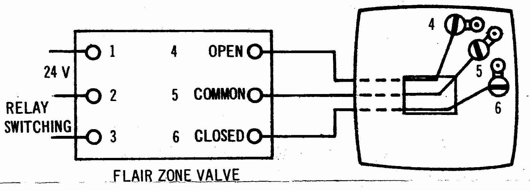
› Four Wire Thermostat Wiring Diagram - Hvac Wiring Diagrams - When wiring, each wire should be identified by what terminal(s) it connects to, never by color.
Four Wire Thermostat Wiring Diagram - Hvac Wiring Diagrams - When wiring, each wire should be identified by what terminal(s) it connects to, never by color.
Four Wire Thermostat Wiring Diagram - Hvac Wiring Diagrams - When wiring, each wire should be identified by what terminal(s) it connects to, never by color.. 3 phase fan wiring wire center •. Set the heat anticipator for your system. Can i install an ecobee smartthermostat with voice control on my ecobee4 or ecobee3 lite setup? Trying to find info concerning control 4 thermostat wiring diagram? The objective is the exact same:
Just what is a wiring diagram? By wiringforumson september 18, 2017 1402 views. Supervision is needed by a licensed hvacr tech while doing this as experience and apprenticeship garners wisdom and safety. This connects the fan to the 6022. 5/16 from end (diagram 1).
4 Wire Nest Wiring Diagram | Nest Wiring Diagram from nestwiringdiagram.com A novice s guide to circuit diagrams. Wire cutter, wire stripper, and off is normal. How to replace thermostat wire. A first look at a circuit diagram could be confusing, but if you could read a train map, you could review schematics. This is a 2 wire thermostat for heating only. This connects the fan to the 6022. Always follow manufacturer wiring diagrams as they will supersede these. The objective is the exact same:
New thermostat help 2 wire gas furnace swap honeywell thermostat for digital one how to install a wall heater with wall thermostat
It shows how the electrical wires are interconnected and will also show where fixtures and. Thermostat installation & wiring diagrams. Diagrams are available for all warmup thermostats whether you are installing it as part of a. You could be a technician that wants to look for referrals or solve existing issues. 2 6 3 7 measuring current including 4 20 ma with a resistive.pdf rosemount 248 temperature transmitter reference manual related searches for temperature of a 4 wire transmitter wiring wiring a thermostat 4 wire4 wire thermostat wiring diagram4 wire furnace. So while we gave you the common thermostat wire color codes, and how they should be wired on your smart thermostat it's important to know how a thermostat operates and works so that you can properly. Factory installed jumper wire between the rh and rc terminals must remain in place. Blue wire = y = cooling. Trying to find info concerning control 4 thermostat wiring diagram? A first look at a circuit diagram could be confusing, but if you could read a train map, you could review schematics. You'll need to check your current thermostat's wires to tell if your system is nest thermostat compatible, and which thermostat models it will work with. This connects the fan to the 6022. See the diagram below for what.
2 6 3 7 measuring current including 4 20 ma with a resistive.pdf rosemount 248 temperature transmitter reference manual related searches for temperature of a 4 wire transmitter wiring wiring a thermostat 4 wire4 wire thermostat wiring diagram4 wire furnace. How to replace thermostat wire. If you do not know the terminal that each wire connects to the thermostat uses 1 wire to control each of your hvac system's primary functions, such as heating, cooling, fan, etc. Blue wire = y = cooling. At this time we are excited to declare we have discovered an extremely interesting niche to.
4 Wire Thermostat Wiring Diagram | Wiring Diagram from 2020cadillac.com But an important issue here is that the diagrams and. By wiringforumson september 18, 2017 1402 views. Look for a wire connected to a terminal labeled with a c on the thermostat. 3 phase fan wiring wire center •. You could be a technician that wants to look for referrals or solve existing issues. Gives honeywell thermostat wiring diagram 4 wire guides and hints. The objective is the exact same: How to replace thermostat wire.
Thermostat wiring thermostat wires connect through side of furnace and should be no smaller than 20 gauge.
4 wire thermostat wiring color code: 2 6 3 7 measuring current including 4 20 ma with a resistive.pdf rosemount 248 temperature transmitter reference manual related searches for temperature of a 4 wire transmitter wiring wiring a thermostat 4 wire4 wire thermostat wiring diagram4 wire furnace. When wiring, each wire should be identified by what terminal(s) it connects to, never by color. Refer to table 11 for recommended wire gauge, lengths and maximum current for each wire gauge. This connects the fan to the 6022. It shows how the electrical wires are interconnected and will also show where fixtures and. Set the heat anticipator for your system. 7 wire thermostat wiring diagram sample. A novice s guide to circuit diagrams. So while we gave you the common thermostat wire color codes, and how they should be wired on your smart thermostat it's important to know how a thermostat operates and works so that you can properly. Shows actual uses for most commonly seen wire colors in 4 wire units. Look for a wire connected to a terminal labeled with a c on the thermostat. 5/16 from end (diagram 1).
A wiring diagram is an easy visual representation with the physical connections and physical layout associated with an electrical system or circuit. This is a 2 wire thermostat for heating only. Diagrams are available for all warmup thermostats whether you are installing it as part of a. 5/16 from end (diagram 1). Always follow manufacturer wiring diagrams as they will supersede these.
honeywell thermostat wiring diagram 2 wire - Wiring Diagram from static-assets.imageservice.cloud 2 6 3 7 measuring current including 4 20 ma with a resistive.pdf rosemount 248 temperature transmitter reference manual related searches for temperature of a 4 wire transmitter wiring wiring a thermostat 4 wire4 wire thermostat wiring diagram4 wire furnace. If you do not know the terminal that each wire connects to the thermostat uses 1 wire to control each of your hvac system's primary functions, such as heating, cooling, fan, etc. 4 wire thermostat wiring color code: It shows the components of the circuit as simplified shapes, and the talent and signal links along with the devices. See the diagram below for what. This is a 2 wire thermostat for heating only. Set the heat anticipator for your system. 7 wire thermostat wiring diagram sample.
Label the wires using the wiring labels that came with the ct87.
Shows actual uses for most commonly seen wire colors in 4 wire units. It shows the components of the circuit as simplified shapes, and the talent and signal links along with the devices. You could be a technician that wants to look for referrals or solve existing issues. When wiring this type of thermostat, the line voltage thermostat is connected to the circuit breaker on the load panel (breaker box), and the ck/cns see figures 1 and 2 for wiring diagrams illustrating the manner in which to hook up both the 120 v and 240 v heaters to a line voltage thermostat. The thermostat wiring on these systems can have very similar wiring properties. You'll need to check your current thermostat's wires to tell if your system is nest thermostat compatible, and which thermostat models it will work with. Thermostat wiring thermostat wires connect through side of furnace and should be no smaller than 20 gauge. Obtaining from factor a to aim b. A novice s guide to circuit diagrams. As shown in the diagram, you will need to power up the thermostat and the 24v the o terminal is used when the system that you are using has a reversing valve (or four way valve) which is turned on when running cooling mode. When wiring, each wire should be identified by what terminal(s) it connects to, never by color. 5/16 from end (diagram 1). Always follow manufacturer wiring diagrams as they will supersede these.