How To Read A Wiring Schematic - 4 Ways To Read Schematics Wikihow - A symbol usually represents a part.. Read how to draw a circuit diagram. But which do you use when creating connections between your symbols? There are a variety of formats for the bom output, depending on how sophisticated your schematic and parts database are, and what kind of output you want. This video shows where to find the wiring schematic for your appliance and what the lines and symbols on the wiring diagram mean so you can figure the third video shows how to trace a circuit on a wiring diagram. The lines between the symbols represents wires that connect the components.
This tutorial should turn you into a fully literate schematic reader! This is an incomplete design just used as a schematic example (not to be built). Note how the holes coloured in orange are connected together. Learning how to read and understand schematics will be easy for beginners with recognizing basic schematic symbols. Understanding how to read and follow schematics is an important skill for any electronics engineer.
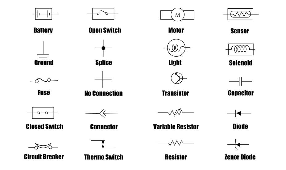
How To Read Car Wiring Diagrams Short Beginners Version Rustyautos Com from rustyautos.com A typical tagging scheme may include combinations of: When a wire splits into two directions, it creates a junction. Junction is when a wire splits into two or more directions, and it creates a junction. How to read a schematic, follow electronics circuit drawings to make actual circuits from them. Once you know how to read an electrical schematic, the next step is to design your own. In order to learn how to read a circuit diagram, it is necessary to learn what the schematic symbol of a component looks like. These schematics can be used by auto mechanics when a free wiring schematic for this car can be found in the cars manuals. Every type of diagram is harder to read the more complex it becomes, not just fritzing.
This includes ac schematics and dc schematics and diagrams that prominently feature relaying.
Type of wiring diagram wiring diagram vs schematic diagram how to read a wiring diagram: Read this guide to start learning how wiring works in starbound and how to use the wiring tools in the game. This is an incomplete design just used as a schematic example (not to be built). These schematics can be used by auto mechanics when a free wiring schematic for this car can be found in the cars manuals. How to wire a breadboard. The completed circuit is known as a net. Knowing how to read circuits is a very useful skill that will help you out all the time. Start with simple schematics and work up to more complicated drawings. A person can also ask for its print out at an auto part store. That is how the tone pots get and the schematic version of one of the poles, for a better visual concept. Read how to draw a circuit diagram. Usually, the electrical wiring diagram of any hvac equipment can be acquired from the manufacturer of this a wiring schematic shows the condition of a piece of equipment when there is no power being applied to the unit. This video shows where to find the wiring schematic for your appliance and what the lines and symbols on the wiring diagram mean so you can figure the third video shows how to trace a circuit on a wiring diagram.
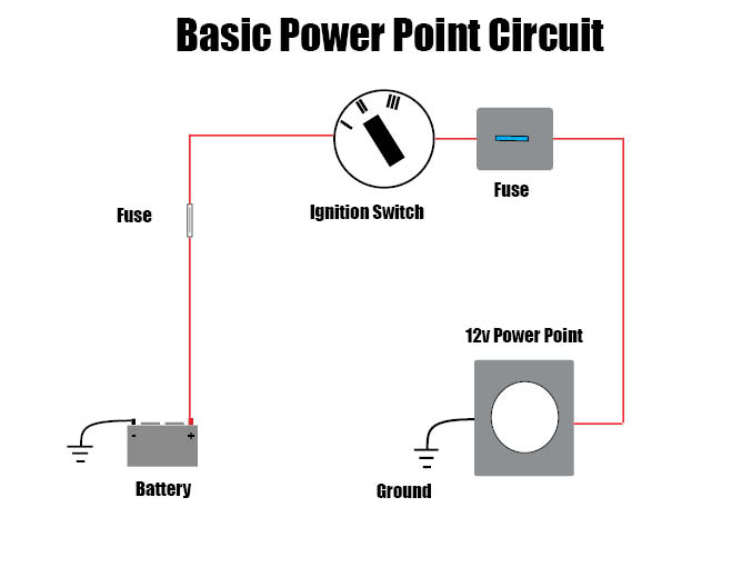
Circuit or schematic diagrams consist of symbols representing physical components and lines representing wires or electrical conductors. Practice is key to learning how to read electrical schematics. This is an incomplete design just used as a schematic example (not to be built). Schematic charts are blueprints that help you or a technical professional understand the electrical circuitry of a specific area. Type of wiring diagram wiring diagram vs schematic diagram how to read a wiring diagram:
How To Read Car Wiring Diagrams For Beginners Emanualonline Blog from blog.emanualonline.com Usually, the electrical wiring diagram of any hvac equipment can be acquired from the manufacturer of this a wiring schematic shows the condition of a piece of equipment when there is no power being applied to the unit. These sets of connecting holes can be called a node, where it's now that you've understood how to establish a simple breadboard circuit connection, here's a tutorial to help you get started with building a. Reading schematics is just a matter of recognizing the symbols and see how they connect. Learning how to read and understand schematics will be easy for beginners with recognizing basic schematic symbols. This physics video tutorial explains how to read a schematic diagram by knowing what each electric symbol represent in a typical. Read this guide to start learning how wiring works in starbound and how to use the wiring tools in the game. This video shows where to find the wiring schematic for your appliance and what the lines and symbols on the wiring diagram mean so you can figure the third video shows how to trace a circuit on a wiring diagram. Understanding how to read and follow schematics is an important skill for any electronics engineer.
There are a variety of formats for the bom output, depending on how sophisticated your schematic and parts database are, and what kind of output you want.
The google images gives me distorted previews i can't read and my dsl is boggy lately, so they won't load in the next few hours. Note that these lines represent conductors, which are the different wires that make up the circuit. Usually, the electrical wiring diagram of any hvac equipment can be acquired from the manufacturer of this a wiring schematic shows the condition of a piece of equipment when there is no power being applied to the unit. An example of a conductive path would be wire or circuit board traces. When a wire splits into two directions, it creates a junction. More advanced schematic drawing tools show a wire hop to make it even more clear that the two nets are not connected. This physics video tutorial explains how to read a schematic diagram by knowing what each electric symbol represent in a typical. Imagine if everyone used different symbols and standards how messy and difficult to understand that would be. This includes ac schematics and dc schematics and diagrams that prominently feature relaying. How it works in standard guitar wiring, the two poles are connected. In order to learn how to read a circuit diagram, it is necessary to learn what the schematic symbol of a component looks like. Except for the ground and vcc symbols which just means connection to supply power. Every type of diagram is harder to read the more complex it becomes, not just fritzing.
Circuit or schematic diagrams consist of symbols representing physical components and lines representing wires or electrical conductors. Here are some of the standard 2. Maybe someone else can take a look and see if one really is right, but i can. How to read schematics : Start with simple schematics and work up to more complicated drawings.
How To Read Car Wiring Diagrams Short Beginners Version Rustyautos Com from rustyautos.com Read this guide to start learning how wiring works in starbound and how to use the wiring tools in the game. Read how to draw a circuit diagram. These sets of connecting holes can be called a node, where it's now that you've understood how to establish a simple breadboard circuit connection, here's a tutorial to help you get started with building a. In order to learn how to read a circuit diagram, it is necessary to learn what the schematic symbol of a component looks like. There always exists the method of brute force drafting and then there are intelligent tools to. Junction is when a wire splits into two or more directions, and it creates a junction. How to read a schematic, follow electronics circuit drawings to make actual circuits from them. Here are some of the standard 2.
The lines between the symbols represents wires that connect the components.
When you're troubleshooting an electrical problem in an appliance, a multimeter. More advanced schematic drawing tools show a wire hop to make it even more clear that the two nets are not connected. The completed circuit is known as a net. How it works in standard guitar wiring, the two poles are connected. This video shows where to find the wiring schematic for your appliance and what the lines and symbols on the wiring diagram mean so you can figure the third video shows how to trace a circuit on a wiring diagram. A person can also ask for its print out at an auto part store. Wires are represented here by green lines indicating. But a junction only means wires passing by but not connected. Junction is when a wire splits into two or more directions, and it creates a junction. Imagine if everyone used different symbols and standards how messy and difficult to understand that would be. Understanding how to read and follow schematics is an important skill for any electronics engineer. When a wire splits into two directions, it creates a junction. Especially if you physically parts are connected by wires, in the diagrams you will see black lines going from one part okay, so now that we've gone through the basics, lets try to read a real world schematic of a circuit.