Control Circuit Diagram - Motor Control Circuits Ladder Logic Electronics Textbook / An ac bulb is used for demonstration.. In this arduino relay control circuit we have used arduino to control the relay via a bc547 transistor. Aug 15, 2017 · arduino stepper motor position control circuit diagram and explanation: Double acting cylinder is used to perform machinng operation. Pneumatic cylinder is advanced by pressing two push buttons simultaneously. Oct 09, 2018 · tv remote control jammer circuit diagram circuit components.
We have connected transistor base to arduino pin a0 through a 1k resistor. Dec 28, 2017 · circuit diagram and working: The circuit is designed to produce a 38 khz signal. Here we discuss about plc pneumatic circuit control with different examples. Audio tone control circuit design:
Electrical And Electronic Drawing Industrial Controls from www.industrial-electronics.com Dec 28, 2017 · circuit diagram and working: To energise the four coils of the stepper motor we are using the digital pins 8,9,10 and 11. Here we discuss about plc pneumatic circuit control with different examples. Oct 09, 2018 · tv remote control jammer circuit diagram circuit components. Double acting cylinder is used to perform machinng operation. The main component in this. In this arduino relay control circuit we have used arduino to control the relay via a bc547 transistor. First, the stop pushbuttons are connected in series to form a nor logic.
Oct 09, 2018 · tv remote control jammer circuit diagram circuit components.
The diagram below illustrates the control circuit needed to accomplish the operation. This control circuit is a variation of the three wire control circuit. Oct 16, 2015 · audio tone control circuit diagram. Oct 09, 2018 · tv remote control jammer circuit diagram circuit components. In this arduino relay control circuit we have used arduino to control the relay via a bc547 transistor. The main component in this. Double acting cylinder is used to perform machinng operation. We have connected transistor base to arduino pin a0 through a 1k resistor. The main purpose of two way switching circuit is that the appliances can be on / off independently from any switch, no matter whatever is the current position of the switch. First, the stop pushbuttons are connected in series to form a nor logic. An ac bulb is used for demonstration. Audio tone control circuit design: A circuit diagram (electrical diagram, elementary diagram, electronic schematic) is a graphical representation of an electrical circuit.a pictorial circuit diagram uses simple images of components, while a schematic diagram shows the components and interconnections of the circuit using standardized symbolic representations.
Plc ladder diagram for single acting and double acting pneumatic cylinders. Pneumatic cylinder is advanced by pressing two push buttons simultaneously. Tv remote jammer circuit design. We have connected transistor base to arduino pin a0 through a 1k resistor. Oct 16, 2015 · audio tone control circuit diagram.
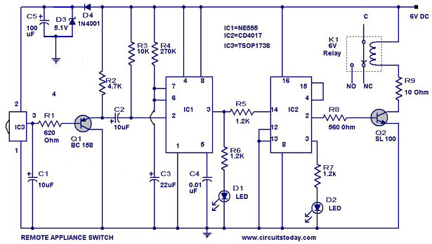
Remote Controlled Appliance Switch Circuit from www.circuitstoday.com We have connected transistor base to arduino pin a0 through a 1k resistor. Oct 16, 2015 · audio tone control circuit diagram. An ac bulb is used for demonstration. Dec 28, 2017 · circuit diagram and working: Tv remote jammer circuit design. The main component in this. In this arduino relay control circuit we have used arduino to control the relay via a bc547 transistor. The 12v adaptor is used for powering the circuit.
An ac bulb is used for demonstration.
An ac bulb is used for demonstration. Design circuit diagram with edrawmax. Oct 09, 2018 · tv remote control jammer circuit diagram circuit components. We have connected transistor base to arduino pin a0 through a 1k resistor. To energise the four coils of the stepper motor we are using the digital pins 8,9,10 and 11. Pneumatic cylinder is advanced by pressing two push buttons simultaneously. Aug 15, 2017 · arduino stepper motor position control circuit diagram and explanation: The main purpose of two way switching circuit is that the appliances can be on / off independently from any switch, no matter whatever is the current position of the switch. This control circuit is a variation of the three wire control circuit. The circuit diagram for the arduino stepper motor control project is shown above. Here we discuss about plc pneumatic circuit control with different examples. In this arduino relay control circuit we have used arduino to control the relay via a bc547 transistor. A circuit diagram (electrical diagram, elementary diagram, electronic schematic) is a graphical representation of an electrical circuit.a pictorial circuit diagram uses simple images of components, while a schematic diagram shows the components and interconnections of the circuit using standardized symbolic representations.
The main component in this. The 12v adaptor is used for powering the circuit. The circuit diagram for the arduino stepper motor control project is shown above. Double acting cylinder is used to perform machinng operation. An ac bulb is used for demonstration.
On Off Infrared Remote Control Circuit Diagram from www.learningelectronics.net Design circuit diagram with edrawmax. The main purpose of two way switching circuit is that the appliances can be on / off independently from any switch, no matter whatever is the current position of the switch. Audio tone control circuit design: Aug 15, 2017 · arduino stepper motor position control circuit diagram and explanation: A circuit diagram (electrical diagram, elementary diagram, electronic schematic) is a graphical representation of an electrical circuit.a pictorial circuit diagram uses simple images of components, while a schematic diagram shows the components and interconnections of the circuit using standardized symbolic representations. Tv remote jammer circuit design. We have connected transistor base to arduino pin a0 through a 1k resistor. Oct 09, 2018 · tv remote control jammer circuit diagram circuit components.
A circuit diagram (electrical diagram, elementary diagram, electronic schematic) is a graphical representation of an electrical circuit.a pictorial circuit diagram uses simple images of components, while a schematic diagram shows the components and interconnections of the circuit using standardized symbolic representations.
Tv remote jammer circuit design. Double acting cylinder is used to perform machinng operation. The circuit diagram for the arduino stepper motor control project is shown above. Oct 16, 2015 · audio tone control circuit diagram. Design circuit diagram with edrawmax. The circuit is designed to produce a 38 khz signal. First, the stop pushbuttons are connected in series to form a nor logic. The main purpose of two way switching circuit is that the appliances can be on / off independently from any switch, no matter whatever is the current position of the switch. Aug 15, 2017 · arduino stepper motor position control circuit diagram and explanation: The 12v adaptor is used for powering the circuit. Dec 28, 2017 · circuit diagram and working: Here we discuss about plc pneumatic circuit control with different examples. Plc ladder diagram for single acting and double acting pneumatic cylinders.