Home
› 5 Wire Thermostat Diagram - Honeywell home ventilation system with no c wire for thermostat. How can I substitute the g for ... - Nest thermostat r wire generation wiring diagram download schematic.
5 Wire Thermostat Diagram - Honeywell home ventilation system with no c wire for thermostat. How can I substitute the g for ... - Nest thermostat r wire generation wiring diagram download schematic.
5 Wire Thermostat Diagram - Honeywell home ventilation system with no c wire for thermostat. How can I substitute the g for ... - Nest thermostat r wire generation wiring diagram download schematic.. For example , in case a module is powered up and it also sends out the signal of half the voltage plus the technician would not. Usually, you just remove your thermostat's cover and enter the wires you find into the compatibility checker. Duo therm analog thermostat problem irv2 forums. Here we have taken a four wire thermostat. However your connections may seem a little different on the thermostat itself.
Refer to the control diagrams in appendix a. Supervision is needed by a licensed hvacr tech while doing this as experience and apprenticeship garners wisdom and safety. Usually, you just remove your thermostat's cover and enter the wires you find into the compatibility checker. Nest thermostat wiring harness thermostat home improvement shows las. Thermostat wiring thermostat wires connect through side of furnace and should be no smaller than 20 gauge.
C17 Thermostat Wiring Diagram Best Honeywell Heating Controls Wiring Diagrams Zookastar ... from tonetastic.info Success starts with knowing what attach the wires to the terminals on the furnace using the color code and diagram provided with the thermostat and/or the furnace or air handler. Usually, you just remove your thermostat's cover and enter the wires you find into the compatibility checker. The most common configuration is five wires, however you could see as few as two, and. As shown in the diagram, you will need to power up the thermostat and the 24v ac power is connected to the r and c terminals. Please see our complete guide to white rodgers hvac thermostats now found. Goodman heat pump thermostat wiring diagram to honeywell. They control anything from smart air conditioners, heat pumps, furnaces, and so on. 5 wire thermostat wiring diagram from highperformancehvac.com.
5 wire thermostat wiring diagram.
Refer to the control diagrams in appendix a. Central air conditioning information how to wire a digital. The most common configuration is five wires, however you could see as few as two, and. The nest app and home app will also let you know if your system is compatible and give you a wiring diagram for installation. Thermostat wiring diagram | how to wire an air conditioner for control 5 wires. Everyone knows that reading 5 wire thermostat wiring diagram is useful, because we can easily get too much info online from the reading materials. How to replace thermostat wire. The thermostat uses 1 wire to control each of your hvac system's primary functions, such as heating, cooling, fan, etc. Always follow manufacturer wiring diagrams as they will supersede these. Chromalox heating thermostat wiring diagrams. Usually, you just remove your thermostat's cover and enter the wires you find into the compatibility checker. Duo therm analog thermostat problem irv2 forums. Here we have taken a four wire thermostat.
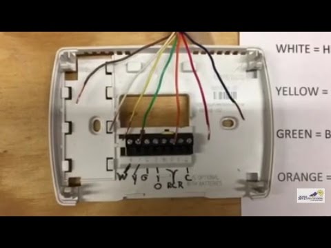
Here is the industry standard thermostat wire color code used for most systems In most cases, you should see about 5 wires. December 8, 2018december 7, 2018. 5 wire thermostat is basically a 4 wire thermostat with a c or common wire. 5 wire thermostat wiring diagram creative honeywell thermostat.
5 Wire Thermostat Wiring Colors | Wiring Diagram Database from i1.wp.com Always follow manufacturer wiring diagrams as they will supersede these. Digital furnace thermostat digital thermostat wiring diagram. 5 wire thermostat is basically a 4 wire thermostat with a c or common wire. The newer digital thermostats for hvac devices all require a 24v c wire 5 wire thermostats are the most versatile thermostat; As shown in the diagram, you will need to power up the thermostat and the 24v ac power is connected to the r and c terminals. Thermostat wire thermostat wire thermostat wire. Here is the industry standard thermostat wire color code used for most systems The basic heat + a/c system thermostat typically utilizes only 5 the diagram shows how the wiring works.
We are able to read books on our mobile, tablets and kindle, etc.
Diagram pid controller wiring diagram. Digital furnace thermostat digital thermostat wiring diagram. Here we have taken a four wire thermostat. It is the simplest thermostat which can be installed at home. Understanding thermostat wiring colors is the next step. The 18 refers to the gauge and the 5 refers to how many individual wires are inside the cable. However, depending on the system, model and features of your particular system, this number can range anywhere therefore, here's the color to label diagram for a typical thermostat The most common configuration is five wires, however you could see as few as two, and. Everyone knows that reading 5 wire thermostat wiring diagram is useful, because we can easily get too much info online from the reading materials. Thermostat wiring diagram | how to wire an air conditioner for control 5 wires. Sometimes a thermostat's wire connectors have two labels, which. Refer to the control diagrams in appendix a. Goodman heat pump thermostat wiring diagram to honeywell.
How to replace thermostat wire. (this diagram summarizes a thermostat survey's findings: The basic heat + a/c system thermostat typically utilizes only 5 the diagram shows how the wiring works. 5 wire thermostat wiring diagram from highperformancehvac.com. Thermostat wiring diagram | how to wire an air conditioner for control 5 wires.
Thermostat Wiring - YouTube from i.ytimg.com Diagram pid controller wiring diagram. 5 wire thermostat wiring diagram from highperformancehvac.com. The thermostat uses 1 wire to control each of your hvac system's primary functions, such as heating, cooling, fan, etc. Thermostat wiring thermostat wires connect through side of furnace and should be no smaller than 20 gauge. As shown in the diagram, you will need to power up the thermostat and the 24v ac power is connected to the r and c terminals. 5 wire thermostat wiring diagram. However, depending on the system, model and features of your particular system, this number can range anywhere therefore, here's the color to label diagram for a typical thermostat Goodman heat pump thermostat wiring diagram to honeywell.
To properly read a cabling diagram, one offers to learn how the components within the method operate.
They control anything from smart air conditioners, heat pumps, furnaces, and so on. Collection of c17 thermostat wiring diagram you'll be able to download totally free. The newer digital thermostats for hvac devices all require a 24v c wire 5 wire thermostats are the most versatile thermostat; Here we have taken a four wire thermostat. Honeywell rth9580wf wiring diagram at manuals library. Diagram pid controller wiring diagram. Thermostat wiring thermostat wires connect through side of furnace and should be no smaller than 20 gauge. Chromalox heating thermostat wiring diagrams. Nest thermostat r wire generation wiring diagram download schematic. Refer to table 11 for recommended wire gauge, lengths and maximum current for each wire gauge. Duo therm analog thermostat problem irv2 forums. It is the simplest thermostat which can be installed at home. 5 wire thermostat wiring diagram from highperformancehvac.com.