Home
› Heat Pump Control Wiring - Wiring Your Radiant System Diy Radiant Floor Heating Radiant Floor Company - These two sources are high voltage and low voltage.
Heat Pump Control Wiring - Wiring Your Radiant System Diy Radiant Floor Heating Radiant Floor Company - These two sources are high voltage and low voltage.
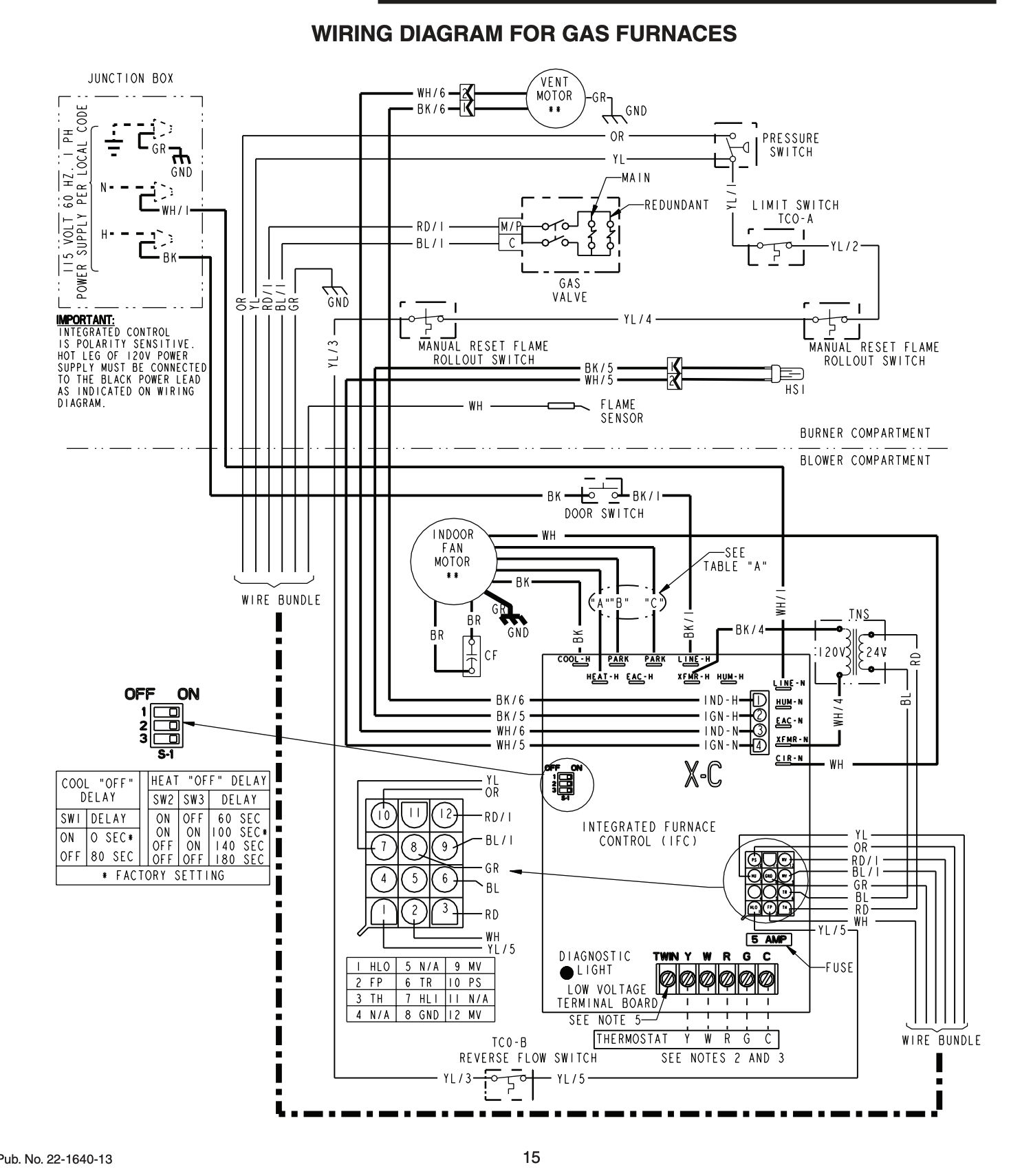
Heat Pump Control Wiring - Wiring Your Radiant System Diy Radiant Floor Heating Radiant Floor Company - These two sources are high voltage and low voltage.. C is known as the common terminal. Using the clamp provided, attach the sensorassembly as shown; It shows the components of the circuit as simplified shapes, and the capability and signal associates with the devices. Db7110u universal heat pump defrost controller application the db7110u universal heat pump defrost controller is a heat pump defrost control used in single stage heat pump appliances. Apply thermal grease(supplied) to the liquid line, where the sensor will bemounted.
Refer to the manufacturer or installing hvac contractor onerewh you should control. Ac150, ac135hp, ac150hp, acrg12, acth12. Mitsubishi ecodan wiring diagram jeep tj 2008 enginee diagrams yenpancane. Each component ought to be set and linked to different parts in specific way. When all the plumbing connections are complete, and ample drying time is allowed, run the filter pump and check the entire system for water leaks.
Trane Hvac Manuals Contact Information from inspectapedia.com This product replaces over 260 oem and competitive controls and can be easily programmed to meet the requirements of virtually any single stage heat pump. This controls the reversing valve that turns a cooling pump into a heat pump. The control wiring is connected to the plus one controlcenter per the field wiring diagrams and figures. There are extra controls in heat pumps that require extra attention and understanding to get the wiring correct. This terminal energizes any factory installed ventilation option.e terminal is the emergency heat input. Make sure filter is clean and there are no obstructions in the filtering system. Goodman pcbdms defrost control board appliance so you can compare the wiring diagrams for the old and new defrost control boards. The last step is choosing the principal thermostat unit or display.
Apply thermal grease(supplied) to the liquid line, where the sensor will bemounted.
If installing on a heat pump unit, attach the liquidline sensor to the liquid line running vertically,directly behind the control box. Apply thermal grease(supplied) to the liquid line, where the sensor will bemounted. This terminal energizes any factory installed ventilation option.e terminal is the emergency heat input. It shows the elements of the circuit as simplified shapes, and the power as well as signal links between the devices. Ac135 air conditioner pdf manual download. This also controls the reversing valve, switching back to the cooling function. This video was produced with a swivl This terminal is activated on a high or low pressure trip by the electronic heat pump control. It reveals the parts of the circuit as simplified shapes, and the power and also signal links between the gadgets. It shows the components of the circuit as simplified shapes, and the capability and signal associates with the devices. For replacement wires use conductors suitable for 105 c. For ampacities and overcurrent protection, see unit rating plate. Each component ought to be set and linked to different parts in specific way.
Be certain that the logo is in the top. Separate relay, or unless the manufacturer has provided wiring to interlock the two. This terminal energizes any factory installed ventilation option.e terminal is the emergency heat input. 14 this diagram is to be used as reference for the low voltage control wiring of your heating and ac system. Assortment of trane heat pump wiring diagram.
Hvac Chillers Heatpump Trane Chiller Air Cooled Control Wiring Diagram Rtaa Series Trane Hvac Cool Stuff from i.pinimg.com (the optional heat pump outdoor temperature sensor between x and w is not installed.) even though it might seem this wiring could lead to the heat pump running when the furnace is on, i believe it is correct for the following reason. Goodman pcbdms defrost control board appliance so you can compare the wiring diagrams for the old and new defrost control boards. Separate relay, or unless the manufacturer has provided wiring to interlock the two. This terminal energizes the emergency heat relay. All parts are inspected for signs of installation upon our receipt of them. Electric backup heat control wiring standard heat pump thermostat variable speed air handler heat pump condenser low voltage connection some ac systems will have a blue wire with a pink stripe in place of the yellow or y wire. The control wiring is connected to the plus one controlcenter per the field wiring diagrams and figures. Each component ought to be set and linked to different parts in specific way.
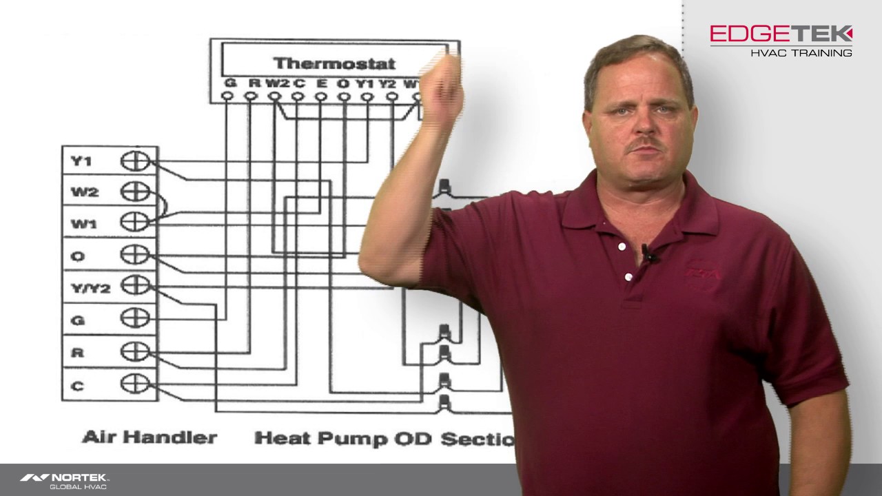
It corresponds to the chart below to explain the thermostat terminal functions.
These two sources are high voltage and low voltage. I discuss the color code and volt. This video was produced with a swivl To fasten, push till you hear clicks. This terminal energizes any factory installed ventilation option.e terminal is the emergency heat input. When completed, wrapthe complete assembly with the insulation tapeprovided. Observe that thermostat aux is connected to furnace w and heat pump x/w. View and download advent ac135 installation and operating instructions manual online. Assortment of carrier heat pump wiring diagram. It corresponds to the chart below to explain the thermostat terminal functions. A wiring diagram is a simplified traditional pictorial depiction of an electrical circuit. Electric backup heat control wiring standard heat pump thermostat variable speed air handler heat pump condenser low voltage connection some ac systems will have a blue wire with a pink stripe in place of the yellow or y wire. This terminal energizes the emergency heat relay.
Assortment of carrier heat pump wiring diagram. Separate relay, or unless the manufacturer has provided wiring to interlock the two. Mitsubishi ecodan wiring diagram jeep tj 2008 enginee diagrams yenpancane. All parts are inspected for signs of installation upon our receipt of them. When all the plumbing connections are complete, and ample drying time is allowed, run the filter pump and check the entire system for water leaks.
Wiring Of A Two Stage Heat Pump Youtube from i.ytimg.com This terminal is activated on a high or low pressure trip by the electronic heat pump control. Split system heat pump (outdoor section) single phase notes: Wiring a heat pump is different than wiring an air conditioner with a gas furnace or boiler. This terminal energizes any factory installed ventilation option.e terminal is the emergency heat input. To fasten, push till you hear clicks. The last step is choosing the principal thermostat unit or display. A wiring diagram is a simplified traditional pictorial depiction of an electrical circuit. Air source heat pump wiring diagram 4r100 car auto9 dxskit1 warmi fr.
Electric backup heat control wiring standard heat pump thermostat variable speed air handler heat pump condenser low voltage connection some ac systems will have a blue wire with a pink stripe in place of the yellow or y wire.
Before uninstalling the old thermostat take a picture of the wiring with your cell phone before removing the wires. Air source heat pump wiring diagram 4r100 car auto9 dxskit1 warmi fr. This video was produced with a swivl The control wiring is connected to the plus one controlcenter per the field wiring diagrams and figures. Split system heat pump (outdoor section) single phase notes: (the optional heat pump outdoor temperature sensor between x and w is not installed.) even though it might seem this wiring could lead to the heat pump running when the furnace is on, i believe it is correct for the following reason. In the goodman heat pump there are two wiring sources that have to be connected. The color of wire r is usually red and c is black. Separate relay, or unless the manufacturer has provided wiring to interlock the two. If installing on a heat pump unit, attach the liquidline sensor to the liquid line running vertically,directly behind the control box. This terminal is activated on a high or low pressure trip by the electronic heat pump control. Air source heat pump wiring diagrams ssr obd ii diagram enginee dxskit1 warmi fr. When completed, wrapthe complete assembly with the insulation tapeprovided.